Showing posts with label buzzer. Show all posts

Wednesday, August 24, 2016

Entry Level Door Monitoring Alarm System

Alright! So the idea struck out of blue one day when I was shocked to see someone sitting outside my office enjoying reading a newspaper!

I had no idea who this person was, when did he come and since how long was he enjoying his unsolicited stay just outside my cabin? You must be thinking what a fool I am but you gotta trust me on this, my office is one of the creepiest that one can get anywhere. Seriously!

I had an Arduino UNO clone ready at my disposal. So, all that I needed was an ultrasound sensor, and a Buzzer. Rest of the steps, circuit assemblies, software code are ensued in this tutorial. I hope this would excite few electronics newbies out there.


Male-to-Male Jumper Wires
1 x Computer with Arduino IDE installed


Optional


Don't have components? Don't worry. Just click the component's name. 


Step 2: Build Your Circuit.


Step 3: Upload The Code.


Download:


Source: here
 
Arduino Arduino UNO R3 buzzer easy project SR04 Ultrasonic Range Finder Ultrasonic Sensor Holder

Friday, August 12, 2016

Arduino Based Mailbox Alert With KY-031 Shock Sensor

Hello world! I made a simple example project for the KY-031 sensor. In this tutorial I made a simple mailbox alert. Of course you can use this code for something else that produces shocks that you want to be notified of.


Step 1: What You Need?

1 x Arduino UNO
1 x USB Type-B Cable 

1 x RGB LED or 3 Color LED Module KY-016 or Other LED 

1 x Shock Sensor KY-031
1 x Buzzer or Buzzer Module KY-012 or PWM Digital I/O Output 5v Buzzer Piezo Module
Female-to-Male Jumper Wires
1 x Computer with Arduino IDE installed

All Sensor Module ( include KY-016, KY-031, KY-012) can be found in 37 Types Sensor in 1 Starter Learning Sensor Kit


Optional
1 x Mini Breadboard
Male-to-Male Jumper Wires 

USB To Power Jack Cable
Multicore Wires 

Don't have components? Don't worry. Just click the component's name. 


Step 2: Build Your Circuit.


Connect wire like the schematic above.


Arduino UNO R3 buzzer easy KY-012 KY-016 KY-031 project RGB LED Shock Sensor Starter Learning Sensor Kit

Arduino Based Earthquake Alarm with KY-002

Hello! Here I am again.

This time I made a Basic earthquake alarm with the KY-002 Shock sensor. Its can be used for multiple purposes, Like most sensors. In this case we use it as a earthquake sensor.


Step 1: What You Need?

1 x Arduino UNO
1 x USB Type-B Cable 

1 x RGB LED or 3 Color LED Module KY-016 

1 x Shock Sensor KY-002 or Arduino Adjustable Vibration Motion Sensor Module 3-pin
1 x Buzzer or Buzzer Module KY-012
Female-to-Male Jumper Wires
1 x Computer with Arduino IDE installed

All Sensor Module ( include KY-016, KY-002, KY-012) can be found in 37 Types Sensor in 1 Starter Learning Sensor Kit


Optional
1 x Mini Breadboard
Male-to-Male Jumper Wires
USB To Power Jack Cable


Don't have components? Don't worry. Just click the component's name. 


Step 2: Build Your Circuit.

Connect wire like the schematic above.


Step 3: Upload The Code.


Arduino UNO R3 buzzer easy KY-002 KY-012 KY-036 project RGB LED sensor Touch Sensor

Thursday, July 28, 2016

Arduino Bluetooth RC Car ( Arduino Phone Controlled)


In this project, I will show you how to transform an RC toy car to Bluetooth controlled through your Android smartphone.


Step 1: What You Need?

1 x USB Type-B Cable
1 x L293D Motor Driver
1 x HC-06 Bluetooth Module 
1 x RC Car that can fit all components 
1 x Computer with Arduino IDE installed
1 x Mini Breadboard 
Male-to-Male Jumper Wires 
Female-to-Male Jumper Wires


Power: 
4 x 1.5V AA Battery  or 
1 x LiOn Rechargeable Battery ( I used an 12V LiOn rechargeable battery)
1 x 4xAA Battery Holder (for AA battery)


Before starting, remove the existing rc circuit.

Now, with one battery AA 1.5V you must find the polarity of 2 c motors.

  • For movement motor (back side) the positive polarity cable will be that moves the car forward.
  • For direction motor (front side) the positive polarity cable will be that moves the wheels left.


Step 3: Build Your Circuit.


Ι suggest you to build your circuit on Mini breadboard first.

You can use on/off switch of car like this:
Battery +........./ .......... Arduino Vin


Tip

If you have a "big" RC car it will need more power so you can use L298 module board. L293D motor driver will give max 0.5A per channel and it will be come very hot after while. L298 module board has a heat sink and can give 1A per channel, but is bigger than L293D.


Step 4: Upload Code To Board.


Download and open file with Arduino IDE. Read every line of code (+comments) to understand how it's working and then upload it to your Arduino uno board!


Step 5: Android Bluetooth Controller.


To control your new Bluetooth car, download and install this android application:


Tip

First enable Bluetooth and establish connection with BT module.
(ex. HC-06, password 1234)
Use "Help & info" button if you can not understand how it is working.

Accelelometer function is under developing, use with attention!

If you have problem with this app on your android device you can also use this one.


Step 6: Test Your Android Bluetooth RC Car. 


Video is in Greek language but I believe that you can understand it...

Thanks for watching!!!

Remember that Bluetooth technology will give you max 15-20 meters of control.


Arduino UNO R3 bluetooth bluetooth module buzzer hc-06 Intermediate l293 L293D l298 L298N LED Lion motor motor driver project RC car rechargeable battery smart car Robot

Friday, July 15, 2016

Play a Melody using the tone() function


This example shows how to use the tone() command to generate notes. It plays a little melody you may have heard before.

Step 1: What You Need?

1 x Arduino Board (Arduino UNO used in this tutorial)
1 x Piezo Buzzer or Speaker
Male-to-Male Jumper Wires 
Female-to-Male Jumper Wires (For Buzzer)

Don't have components? Don't worry. Just click the component's name. 

Step 2: Build Your Circuit.


Step 3: Upload The Code.

1. Select the Arduino board type: Select Tools >> Board >> Select your correct Arduino board used.


2. Find the port number by accessing device manager on Windows. See the section Port (COM&LPT) and look for an open port named "Arduino Uno (COMxx)". If you are using a different board, you will find a name accordingly. What matters is the xx in COMxx part. In my case, it's COM3. So my port number is 3.

Select the right port: Tools >> Port >> Select the port number.


3. You can find this code in the example of Arduino IDE.
Select File >> Examples >> 02.Digital >> toneMelody


Click press the "upload" button (see the button with right arrow mark).
The code below uses an extra file, pitches.h. This file contains all the pitch values for typical notes. For example, NOTE_C4 is middle C. NOTE_FS4 is F sharp, and so forth. This note table was originally written by Brett Hagman, on whose work the tone() command was based. You may find it useful for whenever you want to make musical notes.


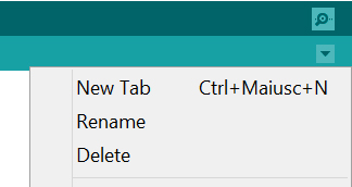
To make the pitches.h file, either click on the button just below the serial monitor icon and choose "New Tab", or use Ctrl+Shift+N. Then paste in the pitches.h code.


Download: 


Arduino Arduino UNO R3 Basic buzzer library speaker

Monday, July 11, 2016

Arduino PIR Motion Sensor Alarm (Simple)


In this project, we'll build a motion-sensing arduino alarm using a PIR (passive infrared) sensor and an Arduino UNO. This is a great way to learn the basics of using digital input (from the sensor) and output (in this case, to a noisy buzzer) on Arduino board. 

This Arduino alarm is handy for booby traps and practical jokes, and it's just what you'll need to detect a zombie invasion! Plus, it's all built on a breadboard, so no soldering required!

1 x Computer with Arduino IDE software


Don't have components? Don't worry. Just click the component's name.

Step 2: Wire Arduino Board To Breadboard.

- Connect digital input/output (I/O) pin 2 on the Arduino UNO to row 1 on the breadboard. (Green color wire)
- Connect the 5V pin on the Arduino UNO to row 2 on the breadboard (Red color wire), and connect a nearby ground (GND) pin to row 3 (Orange color wire).


Step 3: Connect Your Motion Sensor. 

- Find the Gnd (-), Vcc (+), Output pins on the PIR sensor. 


- Plug the PIR sensor into the breadboard so that its (-) pin connects to the Gnd row, its (+) pin connects to 5V, and its Output pin connects to digital pin 2. 


(NOTE: If you have a different sensor that the one shown here, you may need to extend the sensor's pins with a stacking female header, wires, interconnect cables, etc. to fit.)


Step 4: Plug In the LED. 

- Plug the LED's anode (longer leg) into digital pin 13 on the Arduino. 
- Plug the LED's cathode (shorter leg, and/or the leg on the flattened side of the LED base) into the adjacent ground (Gnd) pin on the Arduino. 


Step 5: Connect The Piezo Buzzer. 

- Connect the Vcc on the Buzzer (Red color wire in image) to the Arduino's digital pin 10. 
- Connect the Gnd on the Buzzer (Black color wire in image) to the Arduino's Gnd pin.

(NOTE: These two wires can be reversed, as the polarity of the buzzer doesn't matter.)


Step 6: Program the Arduino. 

- Plug the USB cable into your computer and Arduino UNO. 
- Set the board and port settings for your Arduino Board.
      Board: Arduino UNO
- Open the sketch and upload to board. 


Step 7:Test Your Alarm. 

- When you power up your alarm, the PIR sensor will glow an ominous red. Stand very still or leave the room while the alarm calibrates the infrared level reading for the room. 
- Now test it by moving: the buzzer will buzz and the LED will light up. 
- Be amazed! Your PIR Sensor Arduino Alarm can sense movement up to 20 feet away. 
(NOTE: Might not be reliable for detecting the undead.)


Download: 

Arduino software


Sources:[http://makezine.com/projects/pir-sensor-arduino-alarm/]
Arduino Arduino UNO R3 buzzer easy LED Motion sensor PIR sensor project sensor

Friday, July 08, 2016

Electronic Piano Keyboard With Preset Songs


This is an electronic keyboard with 7 piano keys, programmed to Middle B / A / G / F / E / D / C, and an 8th button used to access a menu of preset songs. 


See how it work:


Step 1: What You Need?

8 x Buttons
1 x 560 Ohm Resistor
1 x Buzzer
1 x Computer with Arduino software installed
Don't have components? Don't worry. Just click the component's name. 

Step 2: Build Your Circuit.

Schematics

Circuit Diagram

Step 3: Upload Code To Board.


(NOTE: Please let me know if you face problem.)


Download: 

Arduino software
Schematic
Circuit Diagram


Sources:[https://create.arduino.cc/projecthub/lindsi8784/electronic-piano-keyboard-with-preset-songs-74ee7c?ref=platform&ref_id=424_trending___&offset=26]

Arduino Arduino UNO R3 beginner button buzzer easy LCD LED Piano project simple

Thursday, July 07, 2016

Arduino Based Obstacle Avoiding Robot


The concept of this project is same as the Detecting Ostacles and HC-SR04 Ultrasonic Sensor.


If the robot detects an object in front of it, with the help of a small servo motor, it scans the area left and right in order to find the best way to turn. It has a notification LED, an buzzer to play a tone when an object is detected and an button for changing the function of the robot (stopped / moving forward). 


Step 1: What You Need?

1 x Micro Servo Motor
1 x Button
1 x Red LED
1 x 220 Ohm Resistor
1 x 9V Battery Holder
1 x Buzzer
8 x Nuts 
8 x Screws 
1 x Smart Robot Car Stainless Steel Metal Robot Chassis Kit 
8 x Spacers (Male-Female)
1 x USB Arduino Cable
1 x 9V Battery 
1 x Computer with Arduino Software installed 
Super Glue
Screw Drive

Optional 
HC-SR04 Ultrasonic Sensor Holder
Hot Gun Glue

Don't have components? Don't worry. Just click the component's name. 

Step 2:Put Hardware Parts On Robot Car


Use the spacers, screws and nuts to attach the Arduino UNO board and the L298 module on robot car. The mini breadboard can be easily attached on the robot car with the adhesive tape that already have at the bottom of it. 

Step 3: The 'Eyes' Of Your Robot


Use super glue to attach the servo motor in the front side of your robot. Watch the first image to understand how to put the ultrasonic sensor in the servo motor by using a small gear piece. The second image shows the completed part that will be the 'eyes' of your robot. 


Step 4: Connect The Circuit


The connections are pretty easy, watch the image above with the breadboard circuit schematic. 

(Tips: Use the breadboard only for the LED, button and buzzer, this will keep it simple and you can use the remain area to add more stuff on the future.)


Step 6: Upload Code To Robot


Plug an battery on it and press the function button once, your robot will start moving forward after upload the code to robot. To stop it, just press the button for one more time. 


You can press the 'Edit' button and start making your modification in the sketch. 
For example, try to change the '10'cm value that is the distance that will make the robot to stop and 'look' for a clear path. 

[Note: If your robot doesn't move forward, try to change the pins of the motors (motorA1 and motorA2 or motorB1 and motorB2)].

Download: 


Sources:[http://www.instructables.com/id/Arduino-Obstacle-Avoiding-Robot-2/?ALLSTEPS]
Arduino Arduino UNO R3 Basic button buzzer easy HC LED project Robot Car sensor servo motor simple SR04 Ultrasonic Range Finder Ultrasonic Sensor Holder

Friday, July 01, 2016

Detecting Obstacles and Warning with Arduino and HC-SR04 Ultrasonic Sensor


This is tutorial to help you understand ultrasonic and buzzer and go deeper into learning Arduino, follow these steps and give me feedback please. It is an easy to make fun project that you can build in 30 minutes or so. Lets get started !!


Step 1: What You Need

1 x Arduino UNO R3
1 x HC-SR04 Ultrasonic Distance Sensor
1 x Buzzer
1 x Breadboard
1 x Arduino USB Cable
1 x Computer with Arduino 
Few Wires

Don't have components? Don't worry. Just click the component's name. 

Step 2: Connect Your Circuit 

Connect the Buzzer POSITIVE terminal to the Arduino pin 2 and the NEGATIVE terminal to the Gnd. Connect the VCC pin of ultrasonic to +5V pin of Arduino board and the Gnd to the ground. Connect trig pin to pin 10 and echo pin to pin 19. The schematic circuit diagram may help you.


Schematic Ciruit Diagram 


Step 3: Upload The Code To Your Arduino 


Download: 


Sources:[https://www.hackster.io/ammaratef45/detecting-obstacles-and-warning-arduino-and-ultrasonic-13e5ea?ref=platform&ref_id=424_trending___&offset=59]
Arduino Arduino UNO R3 Basic beginner buzzer HC sensor simple SR04 Ultrasonic Range Finder


  • Copyright © Arduino Tutorial ™ is a registered trademark.
    Designed by Templateism. Hosted on Blogger Templates.