Showing posts with label 04.Communication. Show all posts

Friday, July 22, 2016

Virtual Color Mixer

This example demonstrates how to send multiple values from the Arduino board to the computer. The readings from three potentiometers are used to set the red, green, and blue components of the background color of a Processing sketch or Max/MSP patch.

Step 1: What You Need?


Don't have components? Don't worry. Just click the component's name. 


Step 2: Build Your Circuit.


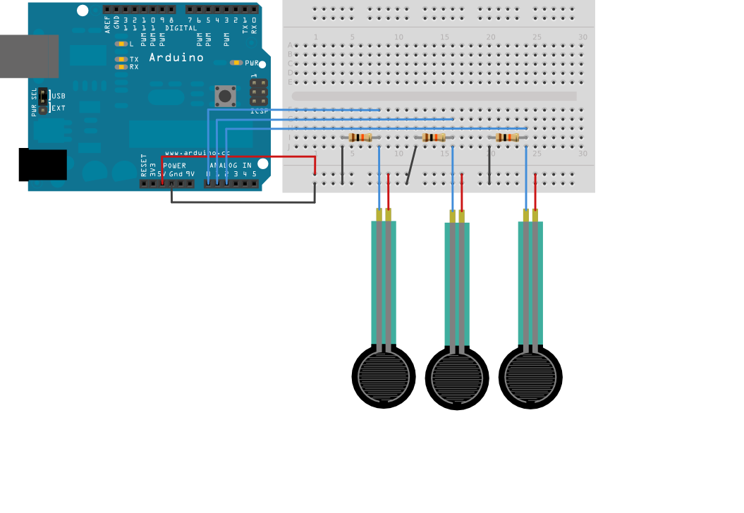
Connect analog sensors to analog input pins 0, 1, and 2.

This circuit uses three voltage divider sub-circuits to generate analog voltages from the force-sensing resistors. A voltage divider has two resistors in series, dividing the voltage proportionally to their values.


Step 3: Upload The Code.


1. Select the Arduino board type: Select Tools >> Board >> Select your correct Arduino board used.


2. Find the port number by accessing device manager on Windows. See the section Port (COM&LPT) and look for an open port named "Arduino Uno (COMxx)". If you are using a different board, you will find a name accordingly. What matters is the xx in COMxx part. In my case, it's COM3. So my port number is 3.


Select the right port: Tools >> Port >> Select the port number.


3. You can find this code in the example of Arduino IDE. 

Select File >> Examples >> 04.Communication >> VirtualColorMixer 

Click press the "upload" button (see the button with right arrow mark).


The sensor values are sent from the Arduino to the computer as ASCII-encoded decimal numbers. This means that each number is sent using the ASCII characters "0" through "9". For the value "234" for example, three bytes are sent: ASCII "2" (binary value 50), ASCII "3" (binary value 51), and ASCII "4" (binary value 52).


Processing Code

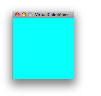
Copy the Processing sketch from the code sample above. As you change the value of the analog sensors, the background color will change:
Max Code

The max patch looks like this. Copy the text of it from the code sample above and paste into a new Max window.
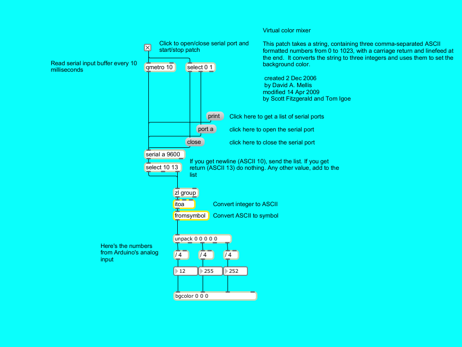


04.Communication library Virtual Color Mixer

Serial Event

This example demonstrates use of the SerialEvent() function. This function is called inside the loop(). If there is serial data in the buffer each character found is added to a string until a newline is found. In this case the string made by the characters received so far is printed and set back to null.


Step 1: What You Need?


1 x Arduino Board ( Arduino UNO R3 used in this tutorial.)
1 x USB Type B cable


Don't have components? Don't worry. Just click the component's name. 


Step 2: Build Your Circuit.


None, but the board has to be connected to the computer; the Arduino Software (IDE) serial monitor may be used to communicate the single or multiple characters and receive the string back.

Step 3: Upload The Code.


1. Select the Arduino board type: Select Tools >> Board >> Select your correct Arduino board used.

2. Find the port number by accessing device manager on Windows. See the section Port (COM&LPT) and look for an open port named "Arduino Uno (COMxx)". If you are using a different board, you will find a name accordingly. What matters is the xx in COMxx part. In my case, it's COM3. So my port number is 3.


Select the right port: Tools >> Port >> Select the port number.

3. You can find this code in the example of Arduino IDE.
Select File >> Examples >> 04.Communication >> SerialEvent


Click press the "upload" button (see the button with right arrow mark).

Download: 


04.Communication library SerialEvent

Serial Call and Response (handshaking) with ASCII-encoded output


This example demonstrates string-based communication from the Arduino board to the computer using a call-and-response (handshaking) method.

The sketch sends an ASCII string on startup and repeats that until it gets a serial response from the computer. Then it sends three sensor values as ASCII-encoded numbers, separated by commas and terminated by a linefeed and carriage return, and waits for another response from the computer.

You can use the Arduino Software (IDE) serial monitor to view the sent data, or it can be read by Processing (see code below), Flash, PD, Max/MSP (see example below), etc. The examples below split the incoming string on the commas and convert the string into numbers again.

Compare this to the Serial call and response example. They are similar, in that both use a handshaking method, but this one encodes the sensor readings as strings, while the other sends them as binary values. While sending as ASCII-encoded strings takes more bytes, it means you can easily send values larger than 255 for each sensor reading. It's also easier to read in a serial terminal program.


Step 1: What You Need?


Don't have components? Don't worry. Just click the component's name. 


Step 2: Build Your Circuit.


Connect analog sensors to analog input pin 0 and 1 with 10K ohm resistors used as voltage dividers. Connect a pushbutton or switch to digital I/O pin 2 with a 10K ohm resistor as a reference to ground.


Step 3: Upload The Code.


1. Select the Arduino board type: Select Tools >> Board >> Select your correct Arduino board used.

2. Find the port number by accessing device manager on Windows. See the section Port (COM&LPT) and look for an open port named "Arduino Uno (COMxx)". If you are using a different board, you will find a name accordingly. What matters is the xx in COMxx part. In my case, it's COM3. So my port number is 3.

Select the right port: Tools >> Port >> Select the port number.

3. You can find this code in the example of Arduino IDE.
Select File >> Examples >> 04.Communication >> SerialCallResponseASCII


Click press the "upload" button (see the button with right arrow mark).

Processing Code

Copy the Processing sketch from the code sample above. As you change the value of the analog sensor, you'll get a ball moving onscreen something like this. The ball will appear only when you push the button:


Max Code

The max patch looks like this. Copy the text from the code sample above and paste it into a new Max window.


Download: 


04.Communication library

Wednesday, July 20, 2016

Serial Call and Response (handshaking)


This example demonstrates multi-byte communication from the Arduino board to the computer using a call-and-response (handshaking) method.

This sketch sends an ASCII A (byte of value 65) on startup and repeats that until it gets a serial response from the computer. Then it sends three sensor values as single bytes, and waits for another response from the computer.

You can use the Arduino Software (IDE) serial monitor to view the sent data, or it can be read by Processing (see code below), Flash, PD, Max/MSP (see example below), etc.


Step 1: What You Need?


Don't have components? Don't worry. Just click the component's name. 


Step 2: Build Your Circuit.


Connect analog sensors to analog input pin 0 and 1 with 10K ohm resistors used as voltage dividers. Connect a pushbutton or switch to digital I/O pin 2 with a 10K ohm resistor as a reference to ground.


Step 3: Upload The Code.


1. Select the Arduino board type: Select Tools >> Board >> Select your correct Arduino board used.

2. Find the port number by accessing device manager on Windows. See the section Port (COM&LPT) and look for an open port named "Arduino Uno (COMxx)". If you are using a different board, you will find a name accordingly. What matters is the xx in COMxx part. In my case, it's COM3. So my port number is 3.

Select the right port: Tools >> Port >> Select the port number.

3. You can find this code in the example of Arduino IDE.
Select File >> Examples >> 04.Communication >> SerialCallResponse 


Click press the "upload" button (see the button with right arrow mark).

Processing Code


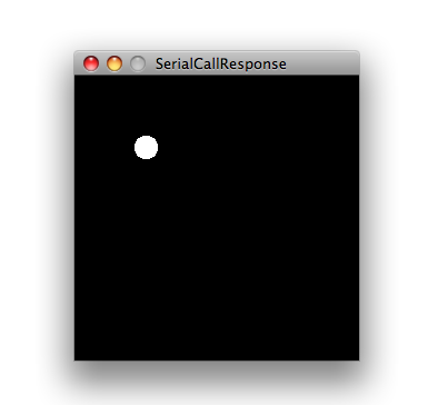
Copy the Processing sketch from the code sample above. As you change the value of the analog sensor, you'll get a ball moving onscreen something like this. The ball will appear only when you push the button:

Max Code


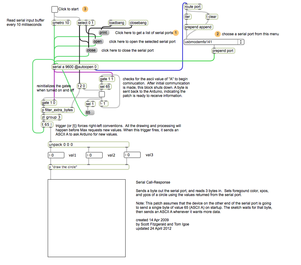
The max patch looks like this. Copy the text from the code sample above.


04.Communication library


  • Copyright © Arduino Tutorial ™ is a registered trademark.
    Designed by Templateism. Hosted on Blogger Templates.