Step 1: What You Need?
1 x Arduino Board ( Arduino UNO R3 used in this tutorial.)
3 x Analog Sensor ( Potentiometer, Photocell, etc.)
3 x 10k Ohm Resistors
1 x Mini Breadboard
1 x USB Type-B Cable
Male-to-Male Jumper Wires
Software Required
Optional
Don't have components? Don't worry. Just click the component's name. 3 x Analog Sensor ( Potentiometer, Photocell, etc.)
3 x 10k Ohm Resistors
1 x Mini Breadboard
1 x USB Type-B Cable
Male-to-Male Jumper Wires
Software Required
Optional
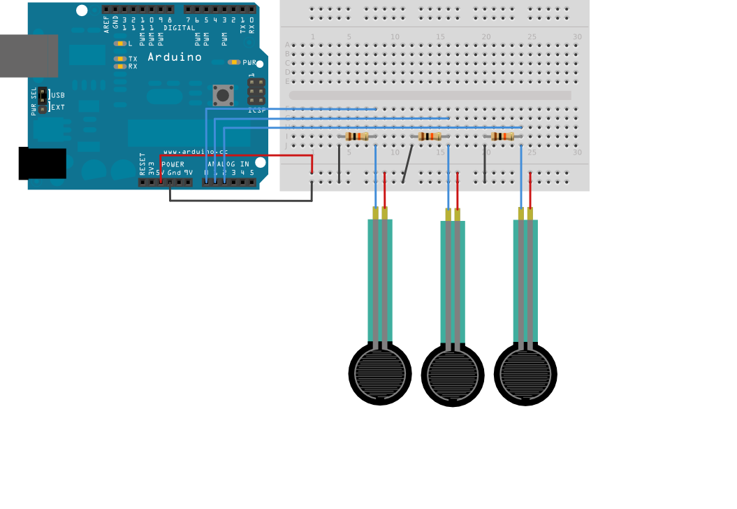
Step 2: Build Your Circuit.
Step 3: Upload The Code.

2. Find the port number by accessing device manager on Windows. See the section Port (COM&LPT) and look for an open port named "Arduino Uno (COMxx)". If you are using a different board, you will find a name accordingly. What matters is the xx in COMxx part. In my case, it's COM3. So my port number is 3.
Select the right port: Tools >> Port >> Select the port number.

3. You can find this code in the example of Arduino IDE.
Select File >> Examples >> 04.Communication >> VirtualColorMixer
Click press the "upload" button (see the button with right arrow mark).
The sensor values are sent from the Arduino to the computer as ASCII-encoded decimal numbers. This means that each number is sent using the ASCII characters "0" through "9". For the value "234" for example, three bytes are sent: ASCII "2" (binary value 50), ASCII "3" (binary value 51), and ASCII "4" (binary value 52).
Processing Code
Copy the Processing sketch from the code sample above. As you change the value of the analog sensors, the background color will change: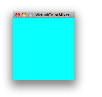
Max Code
The max patch looks like this. Copy the text of it from the code sample above and paste into a new Max window.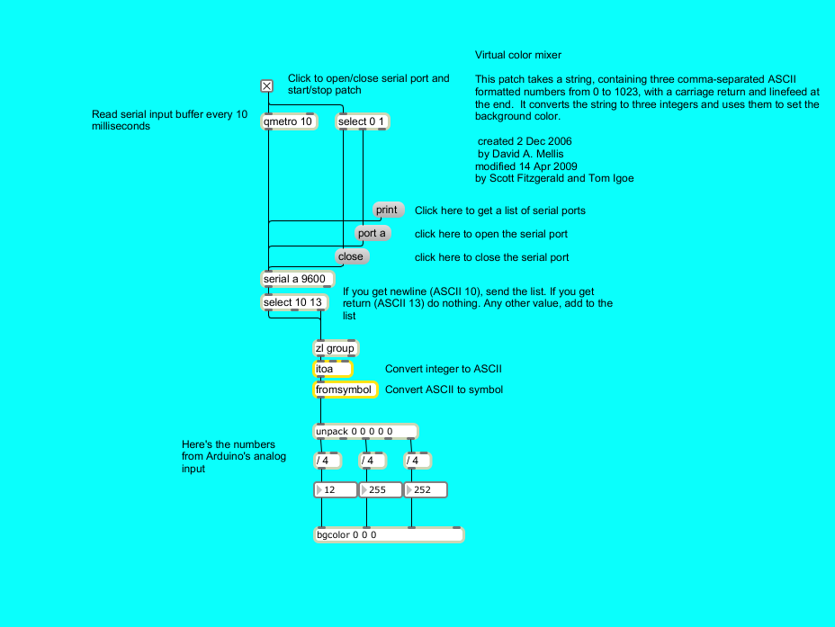

My Robot Education Sdn. Bhd. (Robotedu.my) was founded in 2015 as the first robotics education centre in Malaysia to provide Arduino-based robotics courses for youths. Our vision is to be able to provide robotics education to every youth in Malaysia.


0 comments:
Post a Comment