Showing posts with label simple. Show all posts

Friday, July 08, 2016

Electronic Piano Keyboard With Preset Songs


This is an electronic keyboard with 7 piano keys, programmed to Middle B / A / G / F / E / D / C, and an 8th button used to access a menu of preset songs. 


See how it work:


Step 1: What You Need?

8 x Buttons
1 x 560 Ohm Resistor
1 x Buzzer
1 x Computer with Arduino software installed
Don't have components? Don't worry. Just click the component's name. 

Step 2: Build Your Circuit.

Schematics

Circuit Diagram

Step 3: Upload Code To Board.


(NOTE: Please let me know if you face problem.)


Download: 

Arduino software
Schematic
Circuit Diagram


Sources:[https://create.arduino.cc/projecthub/lindsi8784/electronic-piano-keyboard-with-preset-songs-74ee7c?ref=platform&ref_id=424_trending___&offset=26]

Arduino Arduino UNO R3 beginner button buzzer easy LCD LED Piano project simple

Thursday, July 07, 2016

Arduino Based Obstacle Avoiding Robot


The concept of this project is same as the Detecting Ostacles and HC-SR04 Ultrasonic Sensor.


If the robot detects an object in front of it, with the help of a small servo motor, it scans the area left and right in order to find the best way to turn. It has a notification LED, an buzzer to play a tone when an object is detected and an button for changing the function of the robot (stopped / moving forward). 


Step 1: What You Need?

1 x Micro Servo Motor
1 x Button
1 x Red LED
1 x 220 Ohm Resistor
1 x 9V Battery Holder
1 x Buzzer
8 x Nuts 
8 x Screws 
1 x Smart Robot Car Stainless Steel Metal Robot Chassis Kit 
8 x Spacers (Male-Female)
1 x USB Arduino Cable
1 x 9V Battery 
1 x Computer with Arduino Software installed 
Super Glue
Screw Drive

Optional 
HC-SR04 Ultrasonic Sensor Holder
Hot Gun Glue

Don't have components? Don't worry. Just click the component's name. 

Step 2:Put Hardware Parts On Robot Car


Use the spacers, screws and nuts to attach the Arduino UNO board and the L298 module on robot car. The mini breadboard can be easily attached on the robot car with the adhesive tape that already have at the bottom of it. 

Step 3: The 'Eyes' Of Your Robot


Use super glue to attach the servo motor in the front side of your robot. Watch the first image to understand how to put the ultrasonic sensor in the servo motor by using a small gear piece. The second image shows the completed part that will be the 'eyes' of your robot. 


Step 4: Connect The Circuit


The connections are pretty easy, watch the image above with the breadboard circuit schematic. 

(Tips: Use the breadboard only for the LED, button and buzzer, this will keep it simple and you can use the remain area to add more stuff on the future.)


Step 6: Upload Code To Robot


Plug an battery on it and press the function button once, your robot will start moving forward after upload the code to robot. To stop it, just press the button for one more time. 


You can press the 'Edit' button and start making your modification in the sketch. 
For example, try to change the '10'cm value that is the distance that will make the robot to stop and 'look' for a clear path. 

[Note: If your robot doesn't move forward, try to change the pins of the motors (motorA1 and motorA2 or motorB1 and motorB2)].

Download: 


Sources:[http://www.instructables.com/id/Arduino-Obstacle-Avoiding-Robot-2/?ALLSTEPS]
Arduino Arduino UNO R3 Basic button buzzer easy HC LED project Robot Car sensor servo motor simple SR04 Ultrasonic Range Finder Ultrasonic Sensor Holder

Tuesday, July 05, 2016

Arduino Based Countdown Timer With Setup Buttons


I will show you how to make your own Arduino two digit countdown timer. We will be able to set the timer by pressing the setup buttons. We will use two digits seven segment display, so the maximum countdown time will be 99 seconds. 

Watch the video below:


Step 1: What You Need?

1 x Arduino UNO R3
1 x Mini Breadboard
2 x 7 Segment Displays (You can use common cathode or common anode type)
3 x Buttons
1 x USB Arduino Cable
Wires 
1 x Computer with Arduino Software installed

Don't have components? Don't worry. Just click the component's name. 

Step 2: Built Your Circuit. 


- The segments A-G: 
     A, B, C, D, E, F, G >> 10, 9, 8, 7, 6, 11, 12
- CC* or CA* pins of 7 Segment Displays >> Arduino pin 4 & 5  
- Start/Stop button >> pin 2
- Change button >> pin 3 
- Set button >> pin 13
- Dot pin of RIGHT digit >> pin A0
- Dot pin of LEFT digit >> pin A1

*CC- Common Cathode
*CA- Common Anode

(NOTE: You can connect one 220 Ohm resistor to each pin - except "CC" or "CA" if you want.)

Step 3: Upload Code To Board. 

(NOTE: If you have Common Anode 7 Segment Display type just delete the line 24 "disp.setCommonCathode(),")

Download: 

Arduino software


Sources:[http://www.instructables.com/id/Arduino-Countdown-Timer-With-Setup-Buttons/]
7 segment display Arduino Arduino UNO R3 Basic button countdown easy project simple Timer

Friday, July 01, 2016

Servo Motors and Arduino


Motors are an incredibly important and common component in most projects. There are several different kinds of motors available for you to use, everything from DC motors that simply spin when a voltage is applied to stepper motors that can turn an exact number of spins. 

The main reason I'm not starting with a DC motor or stepper motor is because DC motors typically need a large voltage and current, more than the Arduino board can supply. Stepper motors use a complicated control method that usually requires extra boards and code to control accurately. 


Let's get started.

Step 1: What You Need

1 x Arduino Board (Arduino UNO R3) (can be any kind of Arduino board)
1 x Servo Motor (for this I use Tower Pro 9g SG90)
1 x Computer with Arduino installed 

Don't have components? Don't worry. Just click the component's name. 

Step 2: Build Your Circuit 

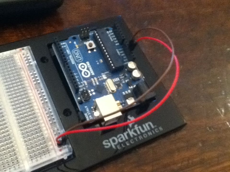
Connect the RED lead from the servo motor to the +5V pin on the Arduino board. Connect the BROWN lead from the servo motor to the 'GND' ground pin on the Arduino board. Connect the YELLOW lead from the servo motor to pin 9 on the Arduino board. 


Step 3: Upload The Code To Arduino 


Download: 

Arduino software


Sources:[http://www.simplesmartdesign.com/arduino-projects-9/]
Arduino Arduino UNO R3 Basic beginner servo motor simple

Detecting Obstacles and Warning with Arduino and HC-SR04 Ultrasonic Sensor


This is tutorial to help you understand ultrasonic and buzzer and go deeper into learning Arduino, follow these steps and give me feedback please. It is an easy to make fun project that you can build in 30 minutes or so. Lets get started !!


Step 1: What You Need

1 x Arduino UNO R3
1 x HC-SR04 Ultrasonic Distance Sensor
1 x Buzzer
1 x Breadboard
1 x Arduino USB Cable
1 x Computer with Arduino 
Few Wires

Don't have components? Don't worry. Just click the component's name. 

Step 2: Connect Your Circuit 

Connect the Buzzer POSITIVE terminal to the Arduino pin 2 and the NEGATIVE terminal to the Gnd. Connect the VCC pin of ultrasonic to +5V pin of Arduino board and the Gnd to the ground. Connect trig pin to pin 10 and echo pin to pin 19. The schematic circuit diagram may help you.


Schematic Ciruit Diagram 


Step 3: Upload The Code To Your Arduino 


Download: 


Sources:[https://www.hackster.io/ammaratef45/detecting-obstacles-and-warning-arduino-and-ultrasonic-13e5ea?ref=platform&ref_id=424_trending___&offset=59]
Arduino Arduino UNO R3 Basic beginner buzzer HC sensor simple SR04 Ultrasonic Range Finder

Blink LED with Arduino


I'm going to show you how to make a simple blink LED with an Arduino with 1-second intervals,as shown below. 


Step 1: What You Need:


1 x Arduino Board (Arduino UNO R3) (it can be any kind, but for this I use the UNO board).
1 x LED (can be any color)
3 x Cables
1 x Computer with Arduino software installed
      Download here: Arduino IDE
1 x Breadboard
1 x USB cable 

Don't have components? Don't worry. Just click the component's name. 


Components requires - Photograph by Instructables

Step 2: Attaching the Power Cables and resistor to the Breadboard


Firstly, you will need to plug one end of a wire into the '5V' power output on the Arduino, and the other end into the Positive section of the breadboard. 
Connect the '5V' Power to breadboard - Photograph by Instructables
Then you need to plug one end of a wire into the Ground ('GND') power output, and the other end into the Negative section of the breadboard. 
Connect the Ground to breadboard - Photograph by Instructables
Finally, you need to plug one end of the resistor from the Negative section of the Breadboard to any horizontal line on the main section. 
(NOTE: It is very important to use AT LEAST a 330 ohm resistor with this circuit. If you don't, then you will almost certainly blow the LED.)
Place resistor on breadboard - Photograph by Instructables

Step 3: Attach the control wire to the Breadboard


Attach a wire from digital port '0' on your Arduino to the hole directly above the resistor. 

Connect control wire to breadbroad - Photograph by Instructables

Step 4: Attaching LED 


Now to attach the LED into the circuit. The way this is done is to put it so that each pin is next to a wire/resistor. This sounds, unclear, but pictures should help you. 
(Be warned, it will NOT do anything until you have uploaded the code to the board, which is done at a later stage.)

You have to put the 'LONGER' pin next to the wire connected to the port, and the 'SHORTER'  pin next to the resistor. 
Place LED to breadbroad - Photograph by Instructables

Step 5: Plug into computer


Now you need to plug the Arduino board into the computer. Nothing really to say here, just make sure that you don't break anything!
Connect Arduino to computer with USB cable - Photograph by Instructables

Step 6: Upload the code to the device


I've attached the code here. All that you have to do is open it with the Arduino sketch program and click upload to device. 

To do this perfectly, you have to ensure the following step:
  1. You have to select the Arduino board type in your IDE. I'm using an Arduino UNO board. To choose the board, find Tools on menu bar. Choose the option "Board" >> select your correct Arduino board. I have chosen the Arduino/Genuino UNO. See the screenshot below. 


 2. The port number is assigned while installing the hardware drive of board. You can find the port number by accessing device manager on Windows. See the section Port (COM&LPT) and look for an open port named "Arduino Uno (COMxx)". If you are using a different board, you will find a name accordingly. What matters is the xx in COMxx part. In my case, it's COM3. So my port number is 3. 
To select the right port, go to Tools >> Port >> Select the port number. Refer screenshot below. 

  3. We are going to upload the verified program in Arduino IDE to the Arduino board. 
To do this, press the "upload" button (see the button with right arrow mark). 


A click on the "upload" button will begin the process of burning the compiled program to Avr mircocontroller on your Arduino board. Depending on the size of your program, this will take a little time. If you look on your Arduino board, you can see the 2 LED's near Tx and Rx blinking. This is an indication of successful communication between your PC and Arduino board. If the program has been uploaded successfully, you will see a message like "Done Uploading". If the uploading process was not successful, you will see an error message accordingly. 

Program Code:


Sources:[http://www.instructables.com/id/Basic-Arduino-Tutorials-01-Blinking-LED/]
Arduino Arduino UNO R3 Basic beginner easy LED simple


  • Copyright © Arduino Tutorial ™ is a registered trademark.
    Designed by Templateism. Hosted on Blogger Templates.