Hey everyone today I want to show you how to make an Arduino-controlled lie detector to see when your friends are lying to you or to measure the different responses that your bodies skin goes through depending on the situation you are in or the emotions you are feeling and the coolest thing of all is that we can see all of theses things happen in real time in an Arduino graph.
Our skin is amazing! It provides a medium for us to experience the sense of touch, it keeps infections out and keeps innards in but I bet you didn't know that our skin changes conductivity depending on many different things one being our mood! It called Electrodermal activity (EDA) and there's a really interesting Wikipedia page you can read here. The basics are that our skin changes its conductivity depending on how we feel.
We have to start by asking the subject some easy questions we know they will answer truthfully like "what is your name" and "where do you live" to get a baseline and from there we can start asking questions that they may lie about, if they do they would probably feel nervous and then we can read the changein the base line that be established earlier if they lie.
Don't have components? Don't worry. Just click the component's name.
Step 2: Build Your Circuit.
The wiring for this is pretty easy, we will start by connecting them in this order:
Connect a long piece of cable to Arduino analog pin 0.
Connect the 2k resistor to ground and the the extended analog 0 pin.
Connect a long piece of cable to Arduino 5 volt pin.
Connect the anode (long leg) of the green led to pin 2 and the cathode (short leg) to ground.
Connect the anode of the orange led to pin 3 and the cathode to ground.
Connect the anode of the red led to pin 4 and the cathode to ground.
That's all the wiring for the Arduino, now we need a way to keep the sensor wires on our fingers we will cover this later.
Step 3: Upload The Code.
The main piece of software we are going use is the newest version on the Arduino IDE. The new update brings a new way to see the data being received from the Arduino, instead of being in text form from the serial monitor, it can now be displayed in a real time graph which will help us identify when the data changes its pattern (when someone lies)
To open the plotter open Arduino and navigate to the tools menu and you should see it there just below serial monitor.
Step 4: Making The Finger Clips.
Now that the basic form of the project is done we can start adding features to make it easier to use we will start by adding finger clips to keep a stable connection between our fingers and the cables.
Lets start by gluing a strip of tinfoil to the bottom of a strip of velcro, do this for both pieces of velcro (the hook and the loop. Now rap it around your finger until it makes a tight fit (check photos) then tape the exposed wire from analog pin 0 to the tin foil and repeat this step for the 5 volt pin (make sure it makes a good connection).
Step 5: Making The Case.
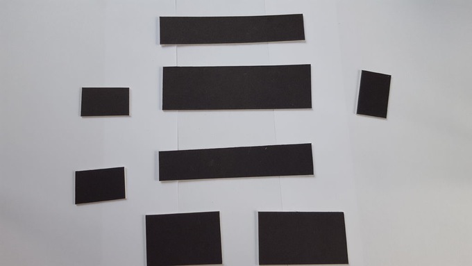
The plan is to make a small compartment for the finger pads to fold away and to have three holes for the LEDs to stick out. Its going to be made out of cardboard and to make it we will need to cut the following shapes out:
Cut two 15x3 cm rectangles
One 15x5 cm rectangle
Three 5x3 cm rectangles (cut a square in the middle on one of them for the nano usb)
One 9x5 cm rectangle
One 6x5 cm rectangle
The 15x5 rectangle is the base. The two 15x3 rectangles and two of the 5x3 rectangles get glued to the sides of the base. Now glue the third 5x3 rectangle to the base 6cm from the side (close to the middle, check photos) Now you should have a rectangle that's divided into two sides, one with a length of 6cm and the other with a length of 9cm. The side with a length of 6cm is where we are going to put the electronics and the other side is where the finger pads go. Next cut 3 holes (the size of LEDs) on the 6x5 rectangle and glue it down to the 6cm side (as a lid). Last we need to tape the short side of the 9x5 rectangle to the far side of the 9cm side (this acts as a lid that flips up and down to reveal the finger pads).
Step 6: Putting It All Together.
The last thing we need to do is put the electronics in the case start by gluing down the Arduino and all wires in the 6cm side and run the extended wires (pin analog 0 and 5 volt) to the other side of of the rectangle (9cm side). Now glue the three LEDs to the holes we made on the 6x5cm rectangle and give it a test if all goes well you should have a small portable Arduino lie detector but let me warn you this isn't the most accurate system in fact most real lie detectors use a host of other sensors to determine if someone is lying such as a heart rate monitor and others, what I'm saying is don't uses the result of this for serious questions.
Don't have components? Don't worry. Just click the component's name.
Step 2: Chassis
See http://letsmakerobots.com/node/37661 for building the base chassis. While 8 leg linkages are obtained from a single kit, you’ll need to use following parts from another kit to complete the chassis:
Motor and body
Axle
Leg linkage case without gears (This is used for joining two independent leg linkages)
Cross beam
Since the built-in battery housing on the body pieces are not needed in my design, cut off about 3mm from the height and glue the platform cardboard on top. Use leftover plastic pieces to build a truss to support the platform above motors and build mounting beams for IR line tracking sensors between two motors.
As for the on-off switch location, I put that on next to the battery pack. This required cutting the plastic underneath the platform. I think the better location would be between the cardboard and the plastic body underneath the cardboard and use a glue gun to secure it.
Step 3: Build Your Circuit.
Wire all the components according to the diagram. You’ll notice that I use 9v step-up boost converter to power Nano through Vin pin. This eliminates having another 9V battery for the logic. Motors are still powered by 6V or 4.8V if using Ni-MH rechargeable batteries.
Step 4: Android Mobile App
While I could have built my own app using MIT App Inventor, why reinvent the wheel when there are numerous already written apps that fit for this purpose? I downloaded few from Google Play to evaluate them and eventually decided to use Arduino Bluetooth Controller. In Controller Mode, I customized following buttons to send specific characters that are recognized by the code.
Left = “l” (turn left)
Right = “r” (turn right)
Up = “u” (go forward)
Down = “d” (go reverse)
X = “s” (stop)
Select = “t” (toggle between RC and Line Following Mode)
Step 5: Upload The Code.
Comments in the code should explain what’s going on in the code. It was written for Nano but it should work on other Arduino boards with no or little mods.
Step 6: Done!
The kit comes with a motor that is designed for low voltage/high current environment. When using an H bridge driver such as TB6612FNG, it’s better to use high voltage/low current motors. This may explain why, with heavier alkaline batteries, it couldn’t lift the body up to take a step.
Donation boxes can be much more interesting and attractive when you combine them with electronics and a little bit of programming. This tutorial will show you how to. As the name explains, making donation boxes interactive can help you gain much more attention and make people happy at the same time! Indeed, and awesome way to set up a charity and help the needed ones by installing it in shopping complexes and other public places (if a bigger version of the same is made). This was just a prototype to present the basic idea which when modified and used at a bigger level, can definitely help.
The following project uses an arduino for all it's processing. The RGB LEDs installed inside the box keep on flashing and changing colors which can attract much attention. When a person donates a coin, the ultrasonic sensor installed just on the box detects that and the servo present at the top waves 2-3 times with a 'Thank You' message displayed. This feature can surely bring a smile on the person's face who just donated that coin! Using only Arduino and some other basic parts, you can make this project within 3-4 hours max. without the need of hunting the parts. Although a bigger version of the same would be much better, but that doesn't mean that this small one is useless. Even this one can be put at various places.
Don't have components? Don't worry. Just click the component's name.
Step 2: Make A Shield For Arduino
The very first step to start this build is to make a shield for Arduino. As I do for all of my projects, making such a shield will greatly help you to make all the connections easy by use of jumper cables. This also eliminates the need of soldering everything up which can sometimes be time consuming. You can just plug in and out your Arduino to be used in other projects at the same time. However, this won't be mandatory for UNO users.
For making the shield, just check for the number of pins on your Arduino and solder the same number of female headers on a piece of perforated board. Check if your Arduino fits in easily. Now solder male headers corresponding to each pin on your Arduino. Add some extra headers 5v and Gnd pins which are more frequently used.
Step 3: Cover Your Box
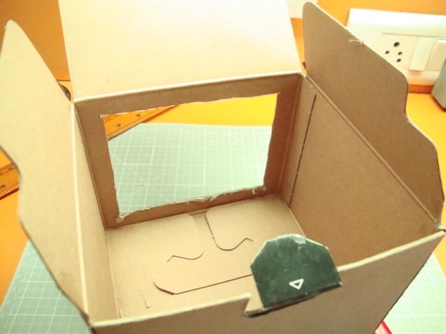
Now moving a little away from electronics, here comes some craft work. You have to now cover your box with some colored paper. But before that, it can be sometimes difficult to find the correct box to suit your needs. If you want to make it just as a project, then the best way is to hunt for shoe boxes, courier boxes or you can even make one from some scrap cardboard. I used a camera box which was just the perfect one.
You can cover the box with any colored paper you want. For making it simple, I used plain brown paper as I don't have much experience and designing skills in art and craft. You can even add some patterns, decorations to make it look more attractive. As for mine, I simply took the measurements, cut the paper and covered all the sides of the box with it.
Step 4: Make The Front Side Transparent
A pretty interesting feature, this can make the box look much better and will also allow to add some LED lighting inside the box. So I chose to cut the front part and cover it with transparent sheet.
You just have leave some of the cardboard to the front side and cut the rest of it (dimensions depend on the size of your box). Cover the cut part with transparent sheet which should be tight and shouldn't sag.
Instead of that thin sheet, you can use acrylic/plexiglass or even ordinary glass to cover the front portion to make the project more permanent. I have no experience on working with glass so chose an easier option.
Step 5: Cut A Coin Slot
This one's very easy. You just have to cut a big coin slot for the coins to be donated inside. Simply cut out a rectangular part measuring about 1.4" x 0.3". It should be big enough for all types of coins to pass through.
Step 6: Mount And Connect The Servo
Now again coming to the electronics part, you have to now mount and connect the servo motor. The purpose of it was to wave whenever a person donated a coin to the box. The best option is to use a standard servo but as you don't have to lift a large weight, even micro servo would work. Also, attach a proper attachment to your servo before connecting it. I used a one sided rotating shaft for the purpose.
Finally, mount the servo at the top using zip ties or hot glue. While mounting, you must take care that the attachment connected to the servo doesn't bang with the cardboard box while moving. In other words, check the angles before mounting it.
Step 7: Solder And Connect The RGB LEDs
Some RGB LEDs are added inside the cardboard box to glow permanently and flash when a coin is added. This makes the box look more cool and adds and awesome feature to it. The light, when glows becomes visible through the front, transparent part thus making the inner coins visible as well. Since one LED would be too dim, I used 4 of them.
First solder all the four LEDs to a piece of perfboard. Connect all the four terminals of each LED in parallel. Please note that the LED type used here is common cathode.
Then, connect the LEDs to Arduino as per the following:
The most important component if this project, this ultrasonic sensor detects when a person donates a coin. Since it can detect distance, when your hand comes near the coin slot, the distances detected by the sensor becomes much less as compared to earlier when there was no obstacle in front of the sensor. For the particular project, we can say that someone donated something when the distance detected by this sensor becomes less than 4cm.
Please note that the sensor used here is NOTHC-SR04 type (the one with four pins). I have used a Ping ultrasonic sensor which has 3 pins connected instead of 4. You can also use the earlier one but only with some modifications in the code. The Ping type sensor can give you much accurate measurement at a faster reaction rate.
Finally, mount the sensor at a distance of approx 2-3cm. Make sure that the sensor doesn't completely touch the base.
Step 9: Upload The Code
Now, upload the code given in the ino file below to your arduino. Be sure to set the correct board and serial port in your IDE before uploading.
Step 10: Finishing Touches
Although not very necessary, it can be worthwhile to add some finishing touches to your project so as to give it a batter look. The only thing that must be added is a little message fixed to the servo which would wave along with the servo shaft. As for me, I used a simple 'Thank You' made using some white paper and stuck to the servo shaft.
Any other quotations, messages, boards and other modifications can be made as well. That depends upon you. Usually, adding some interesting quotes can give you more attention. I tried to keep mine as simple as possible.
Step 11: Powering The Project
The last step is to find a good power source to power your project. The best option is to use a USB charger and connect it straightaway to your Arduino with a USB cable. This would eliminate the need of using a battery and would give you a non-exhausting power supply.
There are various other options as well, like using a 9v battery or a powerbank (as in the image above) to make the project portable. For the battery, connect the positive terminal to Arduino vcc whereas negative terminal to Arduino gnd. Powerbank simply needs to be connected with a USB cable.
Step 12: You're Done!
Now you're finally done making your own interactive donation box! Since this project uses an Arduino, it's completely open-source which means you can make as many modifications as you want. You can even make a bigger version of the same and install it in exhibitions, shopping complex etc. This was just a way to present the basic idea which can be very interesting and beneficial when done on a large scale.
You are free to ask any questions if you want. Don't forget to follow, comment and share it with your friends!