Showing posts with label LED. Show all posts

Wednesday, August 17, 2016

Arduino Based Lie Detector


Hey everyone today I want to show you how to make an Arduino-controlled lie detector to see when your friends are lying to you or to measure the different responses that your bodies skin goes through depending on the situation you are in or the emotions you are feeling and the coolest thing of all is that we can see all of theses things happen in real time in an Arduino graph.


Our skin is amazing! It provides a medium for us to experience the sense of touch, it keeps infections out and keeps innards in but I bet you didn't know that our skin changes conductivity depending on many different things one being our mood! It called Electrodermal activity (EDA) and there's a really interesting Wikipedia page you can read here. The basics are that our skin changes its conductivity depending on how we feel.

We have to start by asking the subject some easy questions we know they will answer truthfully like "what is your name" and "where do you live" to get a baseline and from there we can start asking questions that they may lie about, if they do they would probably feel nervous and then we can read the change
 in the base line that be established earlier if they lie.


Step 1: What You Need?

1 x Arduino Nano
1 x Mini USB Cable
1 x Red LED
1 x Green LED
1 x Orange LED or Yellow LED
1 x 2k Ohm Resistor
Wires


Materials 
- Cardboard
- Tinfoil 
- Velcro 

Tools 
- Soldering Iron & Solder
- Hot Glue 
- Craft Knife 


Don't have components? Don't worry. Just click the component's name. 


Step 2: Build Your Circuit. 

The wiring for this is pretty easy, we will start by connecting them in this order:

  • Connect a long piece of cable to Arduino analog pin 0.
  • Connect the 2k resistor to ground and the the extended analog 0 pin.
  • Connect a long piece of cable to Arduino 5 volt pin.
  • Connect the anode (long leg) of the green led to pin 2 and the cathode (short leg) to ground.
  • Connect the anode of the orange led to pin 3 and the cathode to ground.
  • Connect the anode of the red led to pin 4 and the cathode to ground.

That's all the wiring for the Arduino, now we need a way to keep the sensor wires on our fingers we will cover this later.


Step 3: Upload The Code. 


The main piece of software we are going use is the newest version on the Arduino IDE. The new update brings a new way to see the data being received from the Arduino, instead of being in text form from the serial monitor, it can now be displayed in a real time graph which will help us identify when the data changes its pattern (when someone lies)


To open the plotter open Arduino and navigate to the tools menu and you should see it there just below serial monitor.


Step 4: Making The Finger Clips.


Now that the basic form of the project is done we can start adding features to make it easier to use we will start by adding finger clips to keep a stable connection between our fingers and the cables. 


Lets start by gluing a strip of tinfoil to the bottom of a strip of velcro, do this for both pieces of velcro (the hook and the loop. Now rap it around your finger until it makes a tight fit (check photos) then tape the exposed wire from analog pin 0 to the tin foil and repeat this step for the 5 volt pin (make sure it makes a good connection).


Step 5: Making The Case.


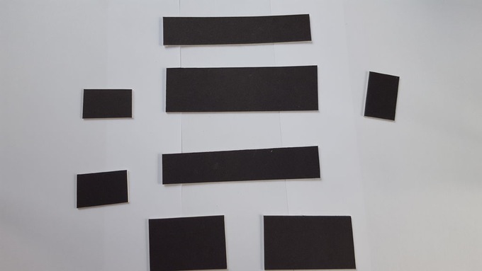
The plan is to make a small compartment for the finger pads to fold away and to have three holes for the LEDs to stick out. Its going to be made out of cardboard and to make it we will need to cut the following shapes out:
  • Cut two 15x3 cm rectangles
  • One 15x5 cm rectangle
  • Three 5x3 cm rectangles (cut a square in the middle on one of them for the nano usb)
  • One 9x5 cm rectangle
  • One 6x5 cm rectangle


The 15x5 rectangle is the base. The two 15x3 rectangles and two of the 5x3 rectangles get glued to the sides of the base. Now glue the third 5x3 rectangle to the base 6cm from the side (close to the middle, check photos) Now you should have a rectangle that's divided into two sides, one with a length of 6cm and the other with a length of 9cm. The side with a length of 6cm is where we are going to put the electronics and the other side is where the finger pads go. Next cut 3 holes (the size of LEDs) on the 6x5 rectangle and glue it down to the 6cm side (as a lid). Last we need to tape the short side of the 9x5 rectangle to the far side of the 9cm side (this acts as a lid that flips up and down to reveal the finger pads).


Step 6: Putting It All Together.


The last thing we need to do is put the electronics in the case start by gluing down the Arduino and all wires in the 6cm side and run the extended wires (pin analog 0 and 5 volt) to the other side of of the rectangle (9cm side). Now glue the three LEDs to the holes we made on the 6x5cm rectangle and give it a test if all goes well you should have a small portable Arduino lie detector but let me warn you this isn't the most accurate system in fact most real lie detectors use a host of other sensors to determine if someone is lying such as a heart rate monitor and others, what I'm saying is don't uses the result of this for serious questions.


Arduino Arduino Nano easy LED project

Sunday, August 14, 2016

Mood Lamp with Arduino

Hi! In this tutorial you will learn to make a mood lamp with Arduino.

I know that you may have seen a lot of mood lamp projects with Arduino, but I wasn't very satisfied with them because they all change the color very abruptly. So, I decided to make a smooth mood lamp and I also made it to turn on only when the room is dark.


This project is good for those who are beginners in the Arduino's world.


Step 1: What You Need?

1 x Arduino UNO
1 x USB Type-B Cable
1 x 9V Battery Holder  or  9V Battery Snap
1 x Breadboard  or  Mini Breadboard
1 x RGB LED  or  1 Red & 1 Green & 1 Blue LED
1 x LDR (Light Dependent Resistor)
Male-to-Male Jumper Wires
1 x Computer with Arduino IDE
1 x 9V Battery
1 x Sheet of paper


Don't have components? Don't worry. Just click the component's name. 


Step 2: Write The Code & Upload. 

Write the code above on the Arduino program.
Darker the ambient light is, the higher is the value read from the LDR.
I used PWM to change led's brightness.


Step 3: Build Your Circuit.

Connect wire like the schematic above.


Step 4: It's done!

Try to add a sheet of paper around it to see it more smoothly, the paper acts as a diffuser.
Feel free to modify this project to your way, and tell me your progress. Comments are welcome.

Arduino UNO R3 easy LDR LED project RGB LED

Tuesday, August 09, 2016

Persistence of Vision (POV) Using Arduino


In this tutorial I will be creating a POV (Persistence of Vision). I'm going to make the POV can be used with two ways to play, easy to hold, and can spinning on the platform.

Ok, let's get started!!


Step 1: What You Need?

1 x USB Type-B Cable 
20 x  LEDs Super Bright  (Green Color LED used in tutorial)
20 x 100 Ohm Resistors
1 x PCB / Perfboard
4 x Spicer (0.5cm)
4 x Nut and Bolts
1 x Project enclosure (I'm using "Kitchen Ware" box)
1 x 9V Battery Holder or 9V Battery Snap
1 x  On/Off Switch 
1 x Breadboard
Shrink Tubing 

Male Header Extended
Male-to-Male Jumper Wires 
Female-to-Male Jumper Wires
1 x Computer with Arduino IDE
1 x 9V Battery

Tools
Soldering Iron and Solder 
Mini Drill 
Pliers 
Cutter 

Optional
Arduino Compatible UNO Ultimate Starter Kit / Learning Kit
USB To Power Jack Cable


Don't have components? Don't worry. Just click the component's name. 


If you want to make your POV spinning too, you need to jump right into step 11 to know what all you need..


Step 2: Write The Code. 

Download the POV code and upload it onto your Arduino board. If you have trouble uploading be sure that nothing is connected to digital pins 0 and 1 and that you have selected the correct board and serial port under the Arduino/Tools menu.

Replace the words HELLO WORLD with any message in all caps with no punctuation. You can create your own characters and images by generating matrices of 1s and 0s.


Download code here: POV


Step 3: Making The Board.

A PCB can be made by many methods like UV etching, toner transfer method, using a CNC mill etc. We’ll be doing it with manually way because the circuit is so simple, and doesn't necessary to print it. it’s the only method which doesn’t require access to expensive equipment/materials.


1) Cut the perfboard, about 22 cm long and 4 cm wide


2) Draw the circuit line with permanent marker. 


3) Etching time! There are a lot of " How to Make PCB Etching" out there, so I won't explain again in this tutorial. 


4) Drill out the holes on perfboard with a drill and a small drill bit. Be careful when using a drill. 


Step 4: Making The Circuit On Breadboard. 

Let's build it on breadboard first. First, lets put the components on a breadboard so we could see how it worked and how to fit it onto the perfboard. 


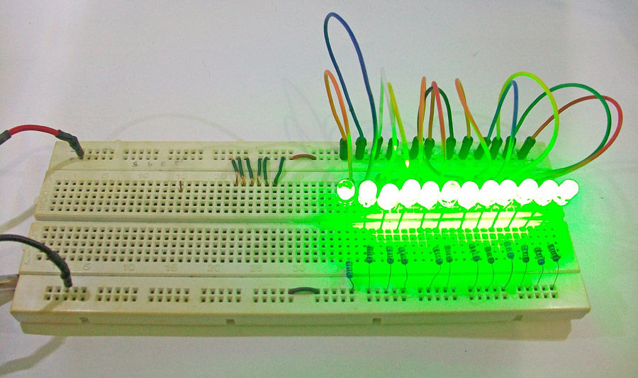
Test the 20 LEDs to make sure they're shining bright. You don't want to pull out the LED after they're already attached on perfboard.


Step 5: Move to Perfboard.

1) Arrange the resistors. Each resistor is connected to an LED on one side and ground on the other. 


2) Bend one of the leads of each resistor so that they are touching each other and solder them all together in a row.


3) Arrange the LEDs. 

4) The cathode (-) of LED connect to resistor, and solder them together.


5) Solder the anode (+) of LED on perfboard. Clip the excess metal from the leads. Leave the last lead unclipped so that it can be attached to a wire later. 


Step 6: Wiring time!!

1) Attach wires to each of the LEDs on the perfboard. As you solder each connection, clip the excess lead off the end of the LED. 


2) Using shrink tubing is essential to prevent shorting.


3) Solder the end of each leads, together with male header (extension). Be careful when you soldering the wire and the header, make sure they didn't touch each other. This will be connect to Arduino. 


4) Strip both ends of a (preferably black) wire and connect the unclipped resistor lead, this is gonna be a ground. Solder it together. 


Step 7: The enclosure

1) Drawing the pattern on the lid with marker for placing the spicer for Arduino. It's really helps for drilling.


2) Be careful when you drilling the "Kitchen Ware" Box, because it made of plastic. It easy to melt if the drill get hot, but it's okay you can tidy it up by using a small cutter knife. Put the spicer 0.5 mm. 


3) Put the Arduino to fit with the lid.


4) Draw a pattern for on-off switch, a long hole for wires, a long hole for insert the perfboard, and 4 holes for nut & bolts. Use a small cutter knife to make a rectangular cut, still be careful.


Step 8: Put all together

1) Drill the perfboard to attach the nut. 


2) Arrange the switch and the battery.


3) Connect the battery and switch to Arduino.


4) Put together the POV perfboard and Arduino.


Pin connections:
Top of perfboard
1                            Digital Pin 13
2                            Digital Pin 12
3                            Digital Pin 11
4                            Digital Pin 10
5                            Digital Pin 9
6 
                           Digital Pin 8
7                            Digital Pin 7
8                            Digital Pin 6
9                            Digital Pin 5
10                          Digital Pin 4
11                          Digital Pin 3
12                          Digital Pin 2
13                          Digital Pin 1
14                          Digital Pin 0
15                          Analog Pin 5
16                          Analog Pin 4
17                          Analog Pin 3
18                          Analog Pin 2
19                          Analog Pin 1
20                          Analog Pin 0
Bottom of perfboard


Step 9: Put the circuit into enclosure.

1) Attach the PCB with nuts to the enclosure. 


2) Tidy up the wires by inserting them to second long hole. 


3) Attach the on-off switch to enclosure. 


4) Put the battery into the enclosure, and connect it to the switch. I'm using "Foam Double Side Tape Adhesive" to attach the battery.


5) Attach the wires to Arduino. And close the enclosure. 


Step 10: Finish!

You're just finish it right away. The enclosure it's make easier to hold and play it safely.


If you are too lazy to holding it all the time, you can choose the second option that I will give it to you. Just check out step 11 to make it spinning.


Step 11: All you need for making it spinning

This is a quick step to make your POV spinning. So here all you need :

- Platform from wood 
you can build it with your own way, for me I just bought it on the market, and it's originally was a cutting board

- 12V motor
I think it's the best choice, because you can run it from 3V to 12V, at 3 volts it only pulled about 20mA and it runs fairly slow, then you can tune your adapter to the speed as fast as you want, but I warned you 12V are fast enough to make your platform shaking like crazy.


- Pencil case from plastic 
I'm using an old pencil case. We're going to use just one side.


- I don't know how to name it or it's called, it's just a bended hard plastic. so we can stick it with the perfboard horizontally. 


Tools
- Drill
- Hot Glue Gun
- Cutter
- Foam double tape adhesive
- Gorilla glue
- Super glue


Step 12: Build the platform board

1) Drill the board. Customize the diameter to the size of the dynamo that you used. 


2) Drill the bended plastic 4 holes as the holes on the perfboard. 


3) As I said before, we're gonna use a one piece of the pencil case. Add a glue (gorilla glue) at the corner to attach the bended plastic. 


4) Soldering the wires to the leads of motor. Don't forget about the polarity. Then attach a little piece of board on the motor with super glue.


5) Put your motor in the hole. Add some gorilla glue onto the little piece of board to attach the pencil case later. 


6) Use a hot glue to attach the motor with the boards. Just to make sure it doesn't shaking when it's run.


7) Attach the pencil case onto motor. You should put on the middle. to keep it balanced. Attach the bended plastic onto the pencil case. And attach the battery with some tape adhesive. Attach the Arduino with some Foam double tape adhesive. 


Step 13: Assemble all parts and Finish it for the second time!!

Assemble all parts. Try the platform first. Give 3 or 4,5 volts from the adapter to make sure they spinning with balancing.


If it's all run okay, then congratulations you just finish the second way to play your POV. Yay!!

Arduino UNO R3 Hard LED Persistence of Vision pov project


  • Copyright © Arduino Tutorial ™ is a registered trademark.
    Designed by Templateism. Hosted on Blogger Templates.