Showing posts with label RGB LED. Show all posts

Tuesday, August 23, 2016

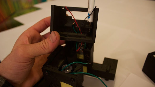
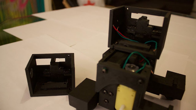
3D Printed and Expandable Robot for Arduino


This is a nice project that you can continue to work on and modify as you learn more Arduino projects. This tutorial goes through the complete build for the bluetooth enabled robot in the first half of the video. It takes in total about 35 hours to 3D print, but can be assembled and programmed in around 30 minutes. Requires only 2 screwdrivers to build and does not require any soldering.

I wanted to design this thing to be inexpensive and use common parts, so this robot uses 9V batteries currently. They run out pretty quickly with a lot of use, so I will probably end up designing a new piece that allows for the use of rechargeable lithium ion batteries and Adafruit power booster. 

Don't have components? Don't worry. Just click the component's name. 


Step 2: Gather 3D Printed Parts

Download 3D printed parts at here or  here.


Step 3: Lightly Sand Wheels and Put Together Legs.


The wheels print in two pieces so use super glue and put them together. Lightly sand out the imperfections. Put the 4 balls inside the castors and push them all the way until they snap into place. Attach the 4 castors to the legs like in the below picture.


Step 4: Get the legs ready and add the geared DC motors.


Get the two posts in the first picture and connect each one to each leg. Get the piece that will hold the battery in the second picture and screw that into one leg. 


Find the small L shaped piece and attach it to a motor exactly like the 4th picture shown above. Do the same thing with the other motor, and attach both to the legs. Meet the two legs together, being sure the motors are facing the same direction and you should have something exactly like the picture below.


Step 5: Add battery with box and complete base.


Find the two curved side pieces in the first picture and connect them to the base according to the second picture. Place the battery box with battery onto the base according to the third picture and find the battery back piece and use it to enclose the battery like the last picture. The base is not complete.


Step 6: Add the middle pieces to the base and add the range sensor and motor driver.


- First use a skinny screwdriver and start the screw in the (robot's) left side middle piece according to the first picture. Its a tight fit and the screw will barely fit under that tab, I have broken the tab off many times, but luckily you have super glue and its an easy fix.


-Pull both battery wires and left side motor wires through the hole and tighten the screw you started. Tighten the second screw and secure the left side piece. Add the faux servo piece to this side and tighten both screws that hold it in, as in the third picture.


-Attach all 4 male to female wires to the HC-SR04 range sensor, it doesn't really matter what colors you use as long as they are different colors and you write down what color goes to what pin on the sensor. 


-Put the range sensor into the whole on the side piece like in the 5th picture and put the L298N motor driver on top. You must remove the two jumpers on the motor driver shown in the 6th picture.


-Attach the wires from the battery and the left side motor to the
 L298N motor driver according to the diagram. Add some male to female (or male to male) wires coming from the positive and negative terminals of the motor driver.


-You will have now two connections in the negative terminal, one going in and one coming out. Just to be clear it will look like the 7th picture (above).


-Grab the right side middle piece and add the other faux servo piece to that side with two screws.


-Now pull the right side motor wires through the right side piece and attach those wires to the motor driver. Try to attach them in order, i.e. left side wire to left most hookup on the driver (same thing on the other side), that way you don't have to change anything in the code later.


-Use two screws to secure the right side piece, and use two screws to secure the motor driver, one per side piece is fine but there are holes to add all 4 if you want.


-Finally, add 6 different color male to female jumper wires to the 6 pins on the motor driver.


Step 7: Almost there.


-Use a screwdriver and add slack to the positive and negative battery wires as shown in the first picture (makes it easier for the battery to slide out the side when you need to change it).


- Attach the claws to the arms and attach those to the shoulder pieces as shown in the first picture. Attach the arms to the faux servo pieces, as in the second picture.


-Find the neck piece in the third picture and attach the C shaped piece (file name neckNoServo.stl) with two screws from the bottom. Pull all the wires through that as
sembly. Attach the neck assembly with 4 screws to the base that you have so far.


-Add the head bottom piece and pull the wires through that try to use the orientation of the wires in the 4th and 5th picture. Range sensor wires through the left most hole (robot's right), motor driver wires through the center, and power and ground through the right most hole. Attach 4 male to female connectors to you bluetooth module and tape them together if possible. It is going to go underneath your Arduino board like in the last picture. This is down so it can be unplugged easily when uploading new sketches.


-Wire everything according to the diagram.


Step 8: Done.


Attach the two halves of the face with 4 screws. Find the ears/antennae and attach them to filename earsNoServo.stl. They should now look like the T shaped pieces in the first picture. Attach them to the head top piece. Each one has two screws. Put the face piece on and pop the LEDs into the eyes, bending the pins at a 90 degree angle so they can't fall off like in the second picture.


Step 9: Upload the code and Download app. 


Download the Android apps in the two pictures below.


Pair your bluetooth module to your computer or phone with the password "1234" it will be called HC-06.Everything else is pretty straight forward to use, if you watched the video, the apps are pretty intuitive to use.

To control the robot via bluetooth from you computer connect the serial monitor to bluetooth port HC-06 and use these commands with CAPITAL LETTERS (put caps lock on) and hit enter after each command:

S = stop, F = forward, B = backward, L = left, and R = right.

IMPORTANT*** anytime you need to upload a new sketch the bluetooth module must be unplugged or else the code will not upload.


Arduino Arduino UNO R3 bluetooth bluetooth module DC Motor with Wheel Hard hc-06 L298N project RGB LED SR04 Ultrasonic Range Finder

Monday, August 22, 2016

Automatic Pet Watering System

The automatic watering system simple just read the water level in the water bowl with a HC-SR04 Ultrasonic Sound Sensor. It measure the distance to the surface of the water. If the level is less then 3cm for more than 30sec it triggers a 5V relay whit a NO-contact . The relay are controlling a 12V DC supply to a mini watering pump in the water tank.


Step 1: What You Need?

1 x Arduino Pro Mini 
1 x General Purpose Transistor NPN ( PN2222A)
1 x Relay (generic) 

1 x Ultrasonic Sensor 
1 x RGB LED (Common Cathode)
1 x LCD 
1 x 12V DC Waterpump 


Don't have components? Don't worry. Just click the component's name. 


Step 2: Build Your Circuit. 


Step 3: Upload The Code. 


You also can view here for more.


1 way channel relay Arduino Arduino Pro Mini Hard HC LCD project Relay RGB LED SR04 Ultrasonic Range Finder

Sunday, August 14, 2016

Mood Lamp with Arduino

Hi! In this tutorial you will learn to make a mood lamp with Arduino.

I know that you may have seen a lot of mood lamp projects with Arduino, but I wasn't very satisfied with them because they all change the color very abruptly. So, I decided to make a smooth mood lamp and I also made it to turn on only when the room is dark.


This project is good for those who are beginners in the Arduino's world.


Step 1: What You Need?

1 x Arduino UNO
1 x USB Type-B Cable
1 x 9V Battery Holder  or  9V Battery Snap
1 x Breadboard  or  Mini Breadboard
1 x RGB LED  or  1 Red & 1 Green & 1 Blue LED
1 x LDR (Light Dependent Resistor)
Male-to-Male Jumper Wires
1 x Computer with Arduino IDE
1 x 9V Battery
1 x Sheet of paper


Don't have components? Don't worry. Just click the component's name. 


Step 2: Write The Code & Upload. 

Write the code above on the Arduino program.
Darker the ambient light is, the higher is the value read from the LDR.
I used PWM to change led's brightness.


Step 3: Build Your Circuit.

Connect wire like the schematic above.


Step 4: It's done!

Try to add a sheet of paper around it to see it more smoothly, the paper acts as a diffuser.
Feel free to modify this project to your way, and tell me your progress. Comments are welcome.

Arduino UNO R3 easy LDR LED project RGB LED

Friday, August 12, 2016

Arduino Based Mailbox Alert With KY-031 Shock Sensor

Hello world! I made a simple example project for the KY-031 sensor. In this tutorial I made a simple mailbox alert. Of course you can use this code for something else that produces shocks that you want to be notified of.


Step 1: What You Need?

1 x Arduino UNO
1 x USB Type-B Cable 

1 x RGB LED or 3 Color LED Module KY-016 or Other LED 

1 x Shock Sensor KY-031
1 x Buzzer or Buzzer Module KY-012 or PWM Digital I/O Output 5v Buzzer Piezo Module
Female-to-Male Jumper Wires
1 x Computer with Arduino IDE installed

All Sensor Module ( include KY-016, KY-031, KY-012) can be found in 37 Types Sensor in 1 Starter Learning Sensor Kit


Optional
1 x Mini Breadboard
Male-to-Male Jumper Wires 

USB To Power Jack Cable
Multicore Wires 

Don't have components? Don't worry. Just click the component's name. 


Step 2: Build Your Circuit.


Connect wire like the schematic above.


Arduino UNO R3 buzzer easy KY-012 KY-016 KY-031 project RGB LED Shock Sensor Starter Learning Sensor Kit

Arduino Based Earthquake Alarm with KY-002

Hello! Here I am again.

This time I made a Basic earthquake alarm with the KY-002 Shock sensor. Its can be used for multiple purposes, Like most sensors. In this case we use it as a earthquake sensor.


Step 1: What You Need?

1 x Arduino UNO
1 x USB Type-B Cable 

1 x RGB LED or 3 Color LED Module KY-016 

1 x Shock Sensor KY-002 or Arduino Adjustable Vibration Motion Sensor Module 3-pin
1 x Buzzer or Buzzer Module KY-012
Female-to-Male Jumper Wires
1 x Computer with Arduino IDE installed

All Sensor Module ( include KY-016, KY-002, KY-012) can be found in 37 Types Sensor in 1 Starter Learning Sensor Kit


Optional
1 x Mini Breadboard
Male-to-Male Jumper Wires
USB To Power Jack Cable


Don't have components? Don't worry. Just click the component's name. 


Step 2: Build Your Circuit.

Connect wire like the schematic above.


Step 3: Upload The Code.


Arduino UNO R3 buzzer easy KY-002 KY-012 KY-036 project RGB LED sensor Touch Sensor

Tuesday, August 09, 2016

Arduino Color Mixer

This tutorial is pretty easy and requires a little Arduino and electronics knowledge, if you're not familiar with Arduino, I'll include links to guide you through the tutorial.

In this tutorial we'll generate all the possible colors that you can see with just a twist. It will also make you see through the RGB color model and understanding how today's displays work.

We'll also use Arduino analog Input / Ouput ( referred to as I/O later in tutorial ) and will learn how to read and write analog voltages on Arduino pins.


Step 1: What You Need?

1 x USB Type-B Cable 
3 x 5k Ohm Potentiometers
3 x 330 Ohm Resistors
1 x RGB LED or RGB Module 
Optional
Cable Cover
Arduino Compatible UNO Ultimate Starter Kit / Learning Kit
USB To Power Jack Cable


Don't have components? Don't worry. Just click the component's name. 


Step 2: Connecting The Pot.

The pot will be our voltage divider circuit, where Vout is the Arduino pin.
Voltage Divider Circuit

In a nutshell, it transforms a adjustable amount of the voltage (changes by twisting the rotor) to the Arduino analog input pin ( Vout ) this link explains the topic even further.


Pot Voltage Divider 


Connect the pot as illustrated in the image, connecting the outer terminals on either 5v or GND doesn't matter at all, the most important connection is the middle terminal, which goes to the analog input pins.

You obtain the 5v and GND from the Arduino pins.

I'm using the Orange for the 5v ( instead of Red ) to make easier to differentiate between power and signal lines.


Repeat this connection for the 3 pots for each color.

I want to keep the connections as tidy as possible so I'll connect the pot for the Red color on A0, Green on A1 and Blue on A2.


Step 3: Connecting The RGB LED.

The RGB LED uses the same concept of the conventional LED (diode) the magic happens because it contains 3 LEDS beside each other, when the light from those LEDs fall on your retina they represent different colors because you view them as a single combined color.


Since we have 256 value for each PWM output and 3 pins that represent Red Green Blue, we have a total of 256 * 256 * 256 colors which is 16,777,216 colors (almost 17 Million).


The RGB Led is connected the same way you'd connect a normal LED but you repeat the work 3 times.

NOTE: Don't forget to connect the 330 Ohm resistor because I made this mistake and got my Red LED burnt out electricity won't do much work to get an LED burnt, so take care.


Step 4: Upload The Code.

 
The code of the Arduino does those simple tasks in a sequential manner.

In the Setup

  • Set the mode of 3 analog input pins to input
  • Set the mode of 3 pwm (analog output) pins to output

In the Loop
  • Read the value of the pot. using analogRead function
  • Map the value from the analog pin to a matching PWM value using the map
  • function
  • Write the PWM value to the analog pin using analogWrite function


Step 5: Test Your Circuit.


Now you have the ultimate color generator with 17M colors! congrats!!


Arduino UNO R3 easy project RGB LED

Sunday, July 31, 2016

Arduino Based Temperature-controlled RGB LED

I'm thinking this could be used for knowing when your hot beverage is at a right temperature to be drunk, or warning when it's getting too cold. Could also work for drinks that are better served chilled!


Step 1: What You Need?

1 x Arduino UNO
1 x USB Type-B Cable
1 x RGB LED
1 x Thermistor
1 x Mini Breadboard
1 x 10k Ohm Resistor
1 x 330 Ohm Resistor
Male-to-Male Jumper Wires
Female-to-Male Jumper Wires
1 x Computer with Arduino IDE installed

Optional
1 x Light Dependent Resistor LDR
Cable Cover
Arduino Compatible UNO Ultimate Starter Kit / Learning Kit
USB To Power Jack Cable


Don't have components? Don't worry. Just click the component's name. 


Step 2: Build Your Circuit.


Arduino UNO R3 easy project RGB LED


  • Copyright © Arduino Tutorial ™ is a registered trademark.
    Designed by Templateism. Hosted on Blogger Templates.