Hello world! Today i made a RFID door lock. The lamp acts as a Electric door lock because i don't have a electrical lock, you simply add the door lock to the relay instead of the lamp. I could not find much about the module, i have the RFID-RC522 in blue color, so this might be useful for the ones who have the same problem as me because the red one has the pins different...
Don't have components? Don't worry. Just click the component's name.
Step 2: Build Your Circuit.
Connect wire like the schematic above.
Step 3: Upload The Code.
You can uncomment this line below (line 68) in the code it will increase reading distance :
mfrc522.PCD_SetAntennaGain(mfrc522.RxGain_max);
Step 4: Test!
There is a button to clear the database. How this works is simple, Just hold the button and reset Arduino. Hold it for 6 second and it will clear all cards added. After that you need to add the new master card and key cards.
This is a really fun and easy project that can be done in about an hour. On the bottom of the skateboard is an accelerometer/gyro with an Arduino board that transmits the angular motion of the board via Bluetooth to a little VR game I made in Unity for Android phones. So, when you turn on your Arduino and the bluetooth connects with your phone, you start moving forward. Lean left and you go left, lean right and you go right. Lift up the front wheels and your character will jump. This only works for Android phones and your phone must be compatible with Google Cardboard. So, if you have an old skateboard laying around, turn it into a virtual reality snowboard.
Don't have components? Don't worry. Just click the component's name.
Step 2: Assemble Your Device
Assemble your device as shown in the picture above.
You will need to solder the header pins onto the MPU-6050, if your soldering iron is new and the tip is clean this can be done in about 11 seconds. If your soldering iron tip is dirty and old this will quickly become the hardest thing you have ever done (speaking from experience).
Make sure the orientation of everything is exactly as shown in the pictures above so you do not have to get into the code and edit anything.
Attach everything to you skateboard EXACTLY as shown (really just make sure the MPU6050 is facing the same direction as the picture).
Here I glued the battery box to the board with hot glue and screwed the Arduino board down. I used an old school board because a wider board is better for the purposes of this experience. It is pretty hard to balance on a board while in virtual reality. The Leonardo works much better for this.
Note: If you are using an Arduino Uno all the connections are the same except: SDA goes to A4 and SCL goes to A5
Step 3: Upload The Code
IMPORTANT: Unplug the RX and TX pins before uploading the code to your board.
You will need to go into your security settings and allow apps to be installed from unknown developers.
Make sure to pair the Bluetooth module to your phone, do not change the default name (HC-06). The password should be 1234.
Notes: If enough people make this I can try to make a better snowboard game, or make an actual skateboard game depending on what I get requests for.
When your turn on your Arduino device make sure the skateboard is flat on the ground and then open the app. As soon as the Bluetooth connects you will drop in.
If the Bluetooth becomes disconnected, restart the app (it is set to connect at the start of the app only, for right now).
This tutorial will illustrate the working of an RFID reader.
What is an RFID reader?
RFID tagging is an ID system that uses small radio frequency identification devices for identification and tracking purposes. An RFID tagging system includes the tag itself, a read/write device, and a host system application for data collection, processing, and transmission.
In simple words an RFID uses electromagnetic fields to transfer data over short distances. You can use an RFID system to open a door. For example, only the person with the right information on his card is allowed to enter.
Don't have components? Don't worry. Just click the component's name.
Step 2: Build Your Circuit.
PinWiring to Arduino Uno
SDA------------------------Digital 10
SCK------------------------Digital 13
MOSI----------------------Digital 11
MISO----------------------Digital 12
IRQ------------------------unconnected
GND-----------------------GND
RST------------------------Digital 9
3.3V------------------------3.3V (DO NOT CONNECT TO 5V)
Step 3: Upload The Code.
After having the circuit ready, go to File > Examples > MFRC522 > DumpInfo and upload the code.
In case you don't have, go to Sketch > Include Library > Manage Libraries..
Then, search MFRC 522 and click install.
/*
* --------------------------------------------------------------------------------------------------------------------
* Example sketch/program showing how to read data from a PICC to serial.
* --------------------------------------------------------------------------------------------------------------------
* This is a MFRC522 library example; for further details and other examples see: https://github.com/miguelbalboa/rfid
*
* Example sketch/program showing how to read data from a PICC (that is: a RFID Tag or Card) using a MFRC522 based RFID
* Reader on the Arduino SPI interface.
*
* When the Arduino and the MFRC522 module are connected (see the pin layout below), load this sketch into Arduino IDE
* then verify/compile and upload it. To see the output: use Tools, Serial Monitor of the IDE (hit Ctrl+Shft+M). When
* you present a PICC (that is: a RFID Tag or Card) at reading distance of the MFRC522 Reader/PCD, the serial output
* will show the ID/UID, type and any data blocks it can read. Note: you may see "Timeout in communication" messages
* when removing the PICC from reading distance too early.
*
* If your reader supports it, this sketch/program will read all the PICCs presented (that is: multiple tag reading).
* So if you stack two or more PICCs on top of each other and present them to the reader, it will first output all
* details of the first and then the next PICC. Note that this may take some time as all data blocks are dumped, so
* keep the PICCs at reading distance until complete.
*
* @license Released into the public domain.
*
* Typical pin layout used:
* -----------------------------------------------------------------------------------------
* MFRC522 Arduino Arduino Arduino Arduino Arduino
* Reader/PCD Uno Mega Nano v3 Leonardo/Micro Pro Micro
* Signal Pin Pin Pin Pin Pin Pin
* -----------------------------------------------------------------------------------------
* RST/Reset RST 9 5 D9 RESET/ICSP-5 RST
* SPI SS SDA(SS) 10 53 D10 10 10
* SPI MOSI MOSI 11 / ICSP-4 51 D11 ICSP-4 16
* SPI MISO MISO 12 / ICSP-1 50 D12 ICSP-1 14
* SPI SCK SCK 13 / ICSP-3 52 D13 ICSP-3 15
*/
#include <SPI.h>
#include <MFRC522.h>
#define RST_PIN 9 // Configurable, see typical pin layout above
#define SS_PIN 10 // Configurable, see typical pin layout above
MFRC522 mfrc522(SS_PIN, RST_PIN); // Create MFRC522 instance
void setup() { Serial.begin(9600);// Initialize serial communications with the PC while (!Serial);// Do nothing if no serial port is opened (added for Arduinos based on ATMEGA32U4) SPI.begin();// Init SPI bus mfrc522.PCD_Init();// Init MFRC522 mfrc522.PCD_DumpVersionToSerial();// Show details of PCD - MFRC522 Card Reader details Serial.println(F("Scan PICC to see UID, type, and data blocks..."));
}
void loop() { // Look for new cards if ( ! mfrc522.PICC_IsNewCardPresent()) { return; } // Select one of the cards if ( ! mfrc522.PICC_ReadCardSerial()) { return; } // Dump debug info about the card; PICC_HaltA() is automatically called mfrc522.PICC_DumpToSerial(&(mfrc522.uid));
}
Step 4: Test & Upload The Code.
Then, open the serial monitor.
You should see something like the figure below: Approximate the RFID card or the keychain to the reader. Let the reader and the tag closer until all the information is displayed.
This is the information that you can read from the card, including the card UID that is highlighted in yellow. The information is stored in the memory that is divided into segments and blocks as you can see in the previous picture.
You have 1024 bytes of data storage divided into 16 sectors and each sector is protected by two different keys, A and B.
Write down your UID card because you’ll need it later.
Upload the Arduino code that has been suffixed here.
/* * * All the resources for this project: https://www.hackster.io/Aritro * Modified by Aritro Mukherjee * * */#include<SPI.h>#include<MFRC522.h>#define SS_PIN 10#define RST_PIN 9MFRC522mfrc522(SS_PIN,RST_PIN);// Create MFRC522 instance.voidsetup(){Serial.begin(9600);// Initiate a serial communicationSPI.begin();// Initiate SPI busmfrc522.PCD_Init();// Initiate MFRC522Serial.println("Approximate your card to the reader...");Serial.println();}voidloop(){// Look for new cardsif(!mfrc522.PICC_IsNewCardPresent()){return;}// Select one of the cardsif(!mfrc522.PICC_ReadCardSerial()){return;}//Show UID on serial monitorSerial.print("UID tag :");Stringcontent="";byteletter;for(bytei=0;i<mfrc522.uid.size;i++){Serial.print(mfrc522.uid.uidByte[i]<0x10?" 0":" ");Serial.print(mfrc522.uid.uidByte[i],HEX);content.concat(String(mfrc522.uid.uidByte[i]<0x10?" 0":" "));content.concat(String(mfrc522.uid.uidByte[i],HEX));}Serial.println();Serial.print("Message : ");content.toUpperCase();if(content.substring(1)=="BD 31 15 2B")//change here the UID of the card/cards that you want to give access{Serial.println("Authorized access");Serial.println();delay(3000);}else{Serial.println(" Access denied");delay(3000);}}
Demonstration
Approximate the card you’ve chosen to give access and you’ll see:
If you approximate another tag with another UID, the denial message will show up:
Download and open file with Arduino IDE. Read every line of code (+comments) to understand how it's working and then upload it to your Arduino uno board!
Step 5: Android Bluetooth Controller.
To control your new Bluetooth car, download and install this android application:
First enable Bluetooth and establish connection with BT module. (ex. HC-06, password 1234) Use "Help & info" button if you can not understand how it is working.
Accelelometer function is under developing, use with attention!
If you have problem with this app on your android device you can also use this one.
Step 6: Test Your Android Bluetooth RC Car.
Video is in Greek language but I believe that you can understand it...
Thanks for watching!!!
Remember that Bluetooth technology will give you max 15-20 meters of control.
Arduino UNO R3bluetoothbluetooth modulebuzzerhc-06Intermediatel293L293Dl298L298NLEDLionmotormotor driverprojectRC carrechargeable batterysmart car Robot
This tutorial will show you how to construct a basic interactive laser-sensitive target, great for those just getting started with Arduino. This could easily be used as a platform for a laser tag system, or just something fun to play with! It might also drive your cat insane.
Don't have components? Don't worry. Just click the component's name.
Step 2: Build Your Circuit.
I built this on a Maker Shield, but you could build this project on anything! This circuit is very straightforward. The four red LEDs are connected to pins 8,9,10,11; the three green LEDs are connected to 2,3,4; and the blue LED is connected to pin 12. (All LEDs are also connected to ground)
The sensor consists of a 5k potentiometer and a photo-resistor. The middle pin on the potentiometer is connected to ground on the Arduino and the other pin on the potentiometer is connected to analogue pin 0, or A0, on the Arduino. The photo-resistor is connected to +3.3 volts on the Arduino and to the A0 pin on the Arduino.
Your almost done!
Step 3: Upload Code To Board.
In it is the program for the Arduino. Now open the file in the Arduino IDE and upload it to your Arduino! Make sure you have the Arduino plugged in to your computer and make sure you have the newest version of Arduino. Once you have the program loaded onto the Arduino, the four red lights should blink on and off in sequence.
Step 4: Have Fun!
Now get a standard 5mw red laser pointer and try pointing it at the photo-resistor! The blue light should turn on and the three green lights should blink on as well. If nothing happens, try adjusting the potentiometer to increase or decrease sensitivity. You can change things in the Arduino program as well. If you are still having issues, let me know in the comments and I might be able to help you.
You could easily use this as a base for a laser tag system with a few modifications to the program. You could also re-program the Arduino to use the green and blue LEDs as a health bar or something. The possibilities are endless! But remember kids, DON'T POINT LASERS IN ANYONE'S EYES!
Don't have components? Don't worry. Just click the component's name.
Step 2: Build Your Circuit.
Using a breadboard, temporarily wire the HC-05 Bluetooth module per the schematic.
With 3.3v on the Key pin, the module will enter 38400 baud command mode and will accept AT commands. The Key pin must be connected to 3.3v when the module is powered on. If it is connected afterwards, the module will enter command mode at the default baud rate (as set by the 'AT+UART=' command or 9600 baud from the factory).
Step 3: Upload Code To Board.
Get the sketch from here and upload it to your Arduino.
Step 4: Run The Setup Sketch & Enter Serial Command.
Open the serial console and make sure the baud rate is set to 9600 and line endings is set to be "Both NL & CR"
Enter the following AT commands into the serial console one by one:
AT+ORGL
AT+ROLE=0
AT+POLAR=1,0
AT+UART=115200,0,0
AT+INIT
In order, these commands tell the module to reset to factory settings, switch to slave role (transparent serial bridge), set pin 32 low on Bluetooth connection, change baud rate to match the Arduino Uno programming rate, and to initialize.
Disconnect 3.3v from the Key pin and cycle the power to the module. It will now be running at 115200 baud and be in pairing mode.
Step 5: Setup The Bluetooth Module in Windows.
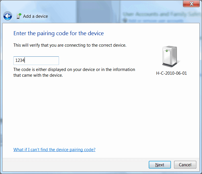
From the Control Panel select Add a Device.
Add the Bluetooth module.
Select enter pairing code option.
Enter "1234" for the pairing code.
At the Add a device success window, click Close.
Device ready to use. The OS will create two serial COM ports associated with the device. Always use the one with the lower number.
Step 6: Solder A Jumper Wires Onto The Bluetooth Module.
DIY Arduino Bluetooth Programming Shield
Disassemble the breadboarded circuit. Solder a jumper wire directly to the HC-05's Pin 32.
Don't forget to use flux.
You may want to use hot glue or tape to protect the joint.
Step 7: Build The Programmer Circuit.
Build the programmer circuit onto the prototyping shield.
Solder on a female header for the Bluetooth module if you want to be able to easily remove it later.
Step 8: Program The Arduino With Bluetooth.
Power on the Arduino from a battery or AC adapter.
In the Arduino IDE, choose the serial port of the Bluetooth module (the lower valued one of the two(21 and 25) and then upload a sketch like normal.