Showing posts with label bluetooth. Show all posts

Tuesday, August 23, 2016

3D Printed and Expandable Robot for Arduino


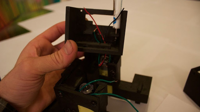
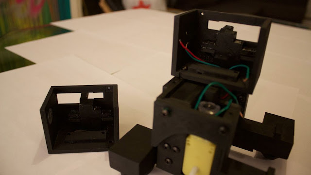
This is a nice project that you can continue to work on and modify as you learn more Arduino projects. This tutorial goes through the complete build for the bluetooth enabled robot in the first half of the video. It takes in total about 35 hours to 3D print, but can be assembled and programmed in around 30 minutes. Requires only 2 screwdrivers to build and does not require any soldering.

I wanted to design this thing to be inexpensive and use common parts, so this robot uses 9V batteries currently. They run out pretty quickly with a lot of use, so I will probably end up designing a new piece that allows for the use of rechargeable lithium ion batteries and Adafruit power booster. 

Don't have components? Don't worry. Just click the component's name. 


Step 2: Gather 3D Printed Parts

Download 3D printed parts at here or  here.


Step 3: Lightly Sand Wheels and Put Together Legs.


The wheels print in two pieces so use super glue and put them together. Lightly sand out the imperfections. Put the 4 balls inside the castors and push them all the way until they snap into place. Attach the 4 castors to the legs like in the below picture.


Step 4: Get the legs ready and add the geared DC motors.


Get the two posts in the first picture and connect each one to each leg. Get the piece that will hold the battery in the second picture and screw that into one leg. 


Find the small L shaped piece and attach it to a motor exactly like the 4th picture shown above. Do the same thing with the other motor, and attach both to the legs. Meet the two legs together, being sure the motors are facing the same direction and you should have something exactly like the picture below.


Step 5: Add battery with box and complete base.


Find the two curved side pieces in the first picture and connect them to the base according to the second picture. Place the battery box with battery onto the base according to the third picture and find the battery back piece and use it to enclose the battery like the last picture. The base is not complete.


Step 6: Add the middle pieces to the base and add the range sensor and motor driver.


- First use a skinny screwdriver and start the screw in the (robot's) left side middle piece according to the first picture. Its a tight fit and the screw will barely fit under that tab, I have broken the tab off many times, but luckily you have super glue and its an easy fix.


-Pull both battery wires and left side motor wires through the hole and tighten the screw you started. Tighten the second screw and secure the left side piece. Add the faux servo piece to this side and tighten both screws that hold it in, as in the third picture.


-Attach all 4 male to female wires to the HC-SR04 range sensor, it doesn't really matter what colors you use as long as they are different colors and you write down what color goes to what pin on the sensor. 


-Put the range sensor into the whole on the side piece like in the 5th picture and put the L298N motor driver on top. You must remove the two jumpers on the motor driver shown in the 6th picture.


-Attach the wires from the battery and the left side motor to the
 L298N motor driver according to the diagram. Add some male to female (or male to male) wires coming from the positive and negative terminals of the motor driver.


-You will have now two connections in the negative terminal, one going in and one coming out. Just to be clear it will look like the 7th picture (above).


-Grab the right side middle piece and add the other faux servo piece to that side with two screws.


-Now pull the right side motor wires through the right side piece and attach those wires to the motor driver. Try to attach them in order, i.e. left side wire to left most hookup on the driver (same thing on the other side), that way you don't have to change anything in the code later.


-Use two screws to secure the right side piece, and use two screws to secure the motor driver, one per side piece is fine but there are holes to add all 4 if you want.


-Finally, add 6 different color male to female jumper wires to the 6 pins on the motor driver.


Step 7: Almost there.


-Use a screwdriver and add slack to the positive and negative battery wires as shown in the first picture (makes it easier for the battery to slide out the side when you need to change it).


- Attach the claws to the arms and attach those to the shoulder pieces as shown in the first picture. Attach the arms to the faux servo pieces, as in the second picture.


-Find the neck piece in the third picture and attach the C shaped piece (file name neckNoServo.stl) with two screws from the bottom. Pull all the wires through that as
sembly. Attach the neck assembly with 4 screws to the base that you have so far.


-Add the head bottom piece and pull the wires through that try to use the orientation of the wires in the 4th and 5th picture. Range sensor wires through the left most hole (robot's right), motor driver wires through the center, and power and ground through the right most hole. Attach 4 male to female connectors to you bluetooth module and tape them together if possible. It is going to go underneath your Arduino board like in the last picture. This is down so it can be unplugged easily when uploading new sketches.


-Wire everything according to the diagram.


Step 8: Done.


Attach the two halves of the face with 4 screws. Find the ears/antennae and attach them to filename earsNoServo.stl. They should now look like the T shaped pieces in the first picture. Attach them to the head top piece. Each one has two screws. Put the face piece on and pop the LEDs into the eyes, bending the pins at a 90 degree angle so they can't fall off like in the second picture.


Step 9: Upload the code and Download app. 


Download the Android apps in the two pictures below.


Pair your bluetooth module to your computer or phone with the password "1234" it will be called HC-06.Everything else is pretty straight forward to use, if you watched the video, the apps are pretty intuitive to use.

To control the robot via bluetooth from you computer connect the serial monitor to bluetooth port HC-06 and use these commands with CAPITAL LETTERS (put caps lock on) and hit enter after each command:

S = stop, F = forward, B = backward, L = left, and R = right.

IMPORTANT*** anytime you need to upload a new sketch the bluetooth module must be unplugged or else the code will not upload.


Arduino Arduino UNO R3 bluetooth bluetooth module DC Motor with Wheel Hard hc-06 L298N project RGB LED SR04 Ultrasonic Range Finder

Monday, August 15, 2016

Enhanced Spider Robot With Arduino Nano


This spider robot is suitable for kids.

My version will have two operating modes:

  • Remote control using bluetooth module (HC-06) and an Android phone app. This is the default start-up mode.
  • Autonomous line-following. This mode is selected through an Android phone app.

Let’s start building.


Step 1: What You Need?

2 x Spider Robot Kit 
4 x Ni-MH Battery/ Charger combo and AA Battery Holder 
2 x IR Line Tracker Sensor Module 
1 x On-Off Switch 
1 x Mini Breadboard
1 x Arduino Nano
1 x Motor Driver ( Using TB6612FNG Breakout but L298x Based driver should work just as well)
1 x HC-06 Bluetooth Module 
1 x 9V Step-up Booster ( 4 x Ni-MH  is only 4.8V). While motors will use 4.8V, I need to boost voltage to 9V to power Nano through Vin)
1 x Mini USB Cable 
Male-to-Male Jumper Wires 
Approx 4" x 4" Cardboard (Used as platform)
1 x Computer with Arduino IDE


See http://letsmakerobots.com/node/37661 for building the base chassis. While 8 leg linkages are obtained from a single kit, you’ll need to use following parts from another kit to complete the chassis:
  • Motor and body
  • Axle
  • Leg linkage case without gears (This is used for joining two independent leg linkages)
  • Cross beam


Since the built-in battery housing on the body pieces are not needed in my design, cut off about 3mm from the height and glue the platform cardboard on top. Use leftover plastic pieces to build a truss to support the platform above motors and build mounting beams for IR line tracking sensors between two motors.


As for the on-off switch location, I put that on next to the battery pack. This required cutting the plastic underneath the platform. I think the better location would be between the cardboard and the plastic body underneath the cardboard and use a glue gun to secure it.


Step 3: Build Your Circuit. 


Wire all the components according to the diagram. You’ll notice that I use 9v step-up boost converter to power Nano through Vin pin. This eliminates having another 9V battery for the logic. Motors are still powered by 6V or 4.8V if using Ni-MH rechargeable batteries.


Step 4: Android Mobile App 


While I could have built my own app using MIT App Inventor, why reinvent the wheel when there are numerous already written apps that fit for this purpose? I downloaded few from Google Play to evaluate them and eventually decided to use Arduino Bluetooth Controller. In Controller Mode, I customized following buttons to send specific characters that are recognized by the code.

  • Left = “l” (turn left)
  • Right = “r” (turn right)
  • Up = “u” (go forward)
  • Down = “d” (go reverse)
  • X = “s” (stop)
  • Select = “t” (toggle between RC and Line Following Mode)


Step 5: Upload The Code.


Comments in the code should explain what’s going on in the code. It was written for Nano but it should work on other Arduino boards with no or little mods.


Step 6: Done! 


The kit comes with a motor that is designed for low voltage/high current environment. When using an H bridge driver such as TB6612FNG, it’s better to use high voltage/low current motors. This may explain why, with heavier alkaline batteries, it couldn’t lift the body up to take a step. 


Arduino Nano bluetooth bluetooth module easy hc-06 IR IR Line Tracker Sensor Module motor driver project Spider Spider Robot Kit

Monday, August 08, 2016

DIY Virtual Reality Skateboard


This is a really fun and easy project that can be done in about an hour. On the bottom of the skateboard is an accelerometer/gyro with an Arduino board that transmits the angular motion of the board via Bluetooth to a little VR game I made in Unity for Android phones. So, when you turn on your Arduino and the bluetooth connects with your phone, you start moving forward. Lean left and you go left, lean right and you go right. Lift up the front wheels and your character will jump. This only works for Android phones and your phone must be compatible with Google Cardboard. So, if you have an old skateboard laying around, turn it into a virtual reality snowboard. 


Step 1: What You Need?

1 x USB Type-B Cable 
1 x HC-06 Bluetooth Module 
1 x MPU-6050 Accelerometer /Gyro
1 x 9V Battery Holder with On/Off Switch 
Male-to-Male Jumper Wires 
Female-to-Male Jumper Wires
1 x Computer with Arduino IDE
1 x Google Cardboard Style Virtual Reality Headset 
1 x Skateboard
4 x Tennis Board ( to keep from rolling away) 
1 x Soldering Iron and Solder
Hot Glue Gun 
Screw And Nuts 

Optional
Cable Cover
Arduino Compatible UNO Ultimate Starter Kit / Learning Kit
USB To Power Jack Cable


Don't have components? Don't worry. Just click the component's name. 


Step 2: Assemble Your Device

Assemble your device as shown in the picture above.

You will need to solder the header pins onto the MPU-6050, if your soldering iron is new and the tip is clean this can be done in about 11 seconds. If your soldering iron tip is dirty and old this will quickly become the hardest thing you have ever done (speaking from experience).

Make sure the orientation of everything is exactly as shown in the pictures above so you do not have to get into the code and edit anything.

Attach everything to you skateboard EXACTLY as shown (really just make sure the MPU6050 is facing the same direction as the picture).


Here I glued the battery box to the board with hot glue and screwed the Arduino board down. I used an old school board because a wider board is better for the purposes of this experience. It is pretty hard to balance on a board while in virtual reality.
The Leonardo works much better for this.

Note: If you are using an Arduino Uno all the connections are the same except:
SDA goes to A4 and SCL goes to A5


Step 3: Upload The Code 


IMPORTANT: Unplug the RX and TX pins before uploading the code to your board. 


Step 4:Download app to your phone


Download apps: Here

You will need to go into your security settings and allow apps to be installed from unknown developers.

Make sure to pair the Bluetooth module to your phone, do not change the default name (HC-06). The password should be 1234.

Notes:
If enough people make this I can try to make a better snowboard game, or make an actual skateboard game depending on what I get requests for.

When your turn on your Arduino device make sure the skateboard is flat on the ground and then open the app. As soon as the Bluetooth connects you will drop in.

If the Bluetooth becomes disconnected, restart the app (it is set to connect at the start of the app only, for right now).


Accelerometer Arduino Leonardo Arduino UNO R3 bluetooth bluetooth module Hard hc-06 Intermediate MPU-6050 project virtual reality

Thursday, July 28, 2016

Arduino Bluetooth RC Car ( Arduino Phone Controlled)


In this project, I will show you how to transform an RC toy car to Bluetooth controlled through your Android smartphone.


Step 1: What You Need?

1 x USB Type-B Cable
1 x L293D Motor Driver
1 x HC-06 Bluetooth Module 
1 x RC Car that can fit all components 
1 x Computer with Arduino IDE installed
1 x Mini Breadboard 
Male-to-Male Jumper Wires 
Female-to-Male Jumper Wires


Power: 
4 x 1.5V AA Battery  or 
1 x LiOn Rechargeable Battery ( I used an 12V LiOn rechargeable battery)
1 x 4xAA Battery Holder (for AA battery)


Before starting, remove the existing rc circuit.

Now, with one battery AA 1.5V you must find the polarity of 2 c motors.

  • For movement motor (back side) the positive polarity cable will be that moves the car forward.
  • For direction motor (front side) the positive polarity cable will be that moves the wheels left.


Step 3: Build Your Circuit.


Ι suggest you to build your circuit on Mini breadboard first.

You can use on/off switch of car like this:
Battery +........./ .......... Arduino Vin


Tip

If you have a "big" RC car it will need more power so you can use L298 module board. L293D motor driver will give max 0.5A per channel and it will be come very hot after while. L298 module board has a heat sink and can give 1A per channel, but is bigger than L293D.


Step 4: Upload Code To Board.


Download and open file with Arduino IDE. Read every line of code (+comments) to understand how it's working and then upload it to your Arduino uno board!


Step 5: Android Bluetooth Controller.


To control your new Bluetooth car, download and install this android application:


Tip

First enable Bluetooth and establish connection with BT module.
(ex. HC-06, password 1234)
Use "Help & info" button if you can not understand how it is working.

Accelelometer function is under developing, use with attention!

If you have problem with this app on your android device you can also use this one.


Step 6: Test Your Android Bluetooth RC Car. 


Video is in Greek language but I believe that you can understand it...

Thanks for watching!!!

Remember that Bluetooth technology will give you max 15-20 meters of control.


Arduino UNO R3 bluetooth bluetooth module buzzer hc-06 Intermediate l293 L293D l298 L298N LED Lion motor motor driver project RC car rechargeable battery smart car Robot


  • Copyright © Arduino Tutorial ™ is a registered trademark.
    Designed by Templateism. Hosted on Blogger Templates.