Alright! So the idea struck out of blue one day when I was shocked to see someone sitting outside my office enjoying reading a newspaper!
I had no idea who this person was, when did he come and since how long was he enjoying his unsolicited stay just outside my cabin? You must be thinking what a fool I am but you gotta trust me on this, my office is one of the creepiest that one can get anywhere. Seriously!
I had an Arduino UNO clone ready at my disposal. So, all that I needed was an ultrasound sensor, and a Buzzer. Rest of the steps, circuit assemblies, software code are ensued in this tutorial. I hope this would excite few electronics newbies out there.
Hey everyone today I want to show you how to make an Arduino-controlled lie detector to see when your friends are lying to you or to measure the different responses that your bodies skin goes through depending on the situation you are in or the emotions you are feeling and the coolest thing of all is that we can see all of theses things happen in real time in an Arduino graph.
Our skin is amazing! It provides a medium for us to experience the sense of touch, it keeps infections out and keeps innards in but I bet you didn't know that our skin changes conductivity depending on many different things one being our mood! It called Electrodermal activity (EDA) and there's a really interesting Wikipedia page you can read here. The basics are that our skin changes its conductivity depending on how we feel.
We have to start by asking the subject some easy questions we know they will answer truthfully like "what is your name" and "where do you live" to get a baseline and from there we can start asking questions that they may lie about, if they do they would probably feel nervous and then we can read the changein the base line that be established earlier if they lie.
Don't have components? Don't worry. Just click the component's name.
Step 2: Build Your Circuit.
The wiring for this is pretty easy, we will start by connecting them in this order:
Connect a long piece of cable to Arduino analog pin 0.
Connect the 2k resistor to ground and the the extended analog 0 pin.
Connect a long piece of cable to Arduino 5 volt pin.
Connect the anode (long leg) of the green led to pin 2 and the cathode (short leg) to ground.
Connect the anode of the orange led to pin 3 and the cathode to ground.
Connect the anode of the red led to pin 4 and the cathode to ground.
That's all the wiring for the Arduino, now we need a way to keep the sensor wires on our fingers we will cover this later.
Step 3: Upload The Code.
The main piece of software we are going use is the newest version on the Arduino IDE. The new update brings a new way to see the data being received from the Arduino, instead of being in text form from the serial monitor, it can now be displayed in a real time graph which will help us identify when the data changes its pattern (when someone lies)
To open the plotter open Arduino and navigate to the tools menu and you should see it there just below serial monitor.
Step 4: Making The Finger Clips.
Now that the basic form of the project is done we can start adding features to make it easier to use we will start by adding finger clips to keep a stable connection between our fingers and the cables.
Lets start by gluing a strip of tinfoil to the bottom of a strip of velcro, do this for both pieces of velcro (the hook and the loop. Now rap it around your finger until it makes a tight fit (check photos) then tape the exposed wire from analog pin 0 to the tin foil and repeat this step for the 5 volt pin (make sure it makes a good connection).
Step 5: Making The Case.
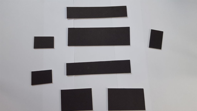
The plan is to make a small compartment for the finger pads to fold away and to have three holes for the LEDs to stick out. Its going to be made out of cardboard and to make it we will need to cut the following shapes out:
Cut two 15x3 cm rectangles
One 15x5 cm rectangle
Three 5x3 cm rectangles (cut a square in the middle on one of them for the nano usb)
One 9x5 cm rectangle
One 6x5 cm rectangle
The 15x5 rectangle is the base. The two 15x3 rectangles and two of the 5x3 rectangles get glued to the sides of the base. Now glue the third 5x3 rectangle to the base 6cm from the side (close to the middle, check photos) Now you should have a rectangle that's divided into two sides, one with a length of 6cm and the other with a length of 9cm. The side with a length of 6cm is where we are going to put the electronics and the other side is where the finger pads go. Next cut 3 holes (the size of LEDs) on the 6x5 rectangle and glue it down to the 6cm side (as a lid). Last we need to tape the short side of the 9x5 rectangle to the far side of the 9cm side (this acts as a lid that flips up and down to reveal the finger pads).
Step 6: Putting It All Together.
The last thing we need to do is put the electronics in the case start by gluing down the Arduino and all wires in the 6cm side and run the extended wires (pin analog 0 and 5 volt) to the other side of of the rectangle (9cm side). Now glue the three LEDs to the holes we made on the 6x5cm rectangle and give it a test if all goes well you should have a small portable Arduino lie detector but let me warn you this isn't the most accurate system in fact most real lie detectors use a host of other sensors to determine if someone is lying such as a heart rate monitor and others, what I'm saying is don't uses the result of this for serious questions.
Don't have components? Don't worry. Just click the component's name.
Step 2: Chassis
See http://letsmakerobots.com/node/37661 for building the base chassis. While 8 leg linkages are obtained from a single kit, you’ll need to use following parts from another kit to complete the chassis:
Motor and body
Axle
Leg linkage case without gears (This is used for joining two independent leg linkages)
Cross beam
Since the built-in battery housing on the body pieces are not needed in my design, cut off about 3mm from the height and glue the platform cardboard on top. Use leftover plastic pieces to build a truss to support the platform above motors and build mounting beams for IR line tracking sensors between two motors.
As for the on-off switch location, I put that on next to the battery pack. This required cutting the plastic underneath the platform. I think the better location would be between the cardboard and the plastic body underneath the cardboard and use a glue gun to secure it.
Step 3: Build Your Circuit.
Wire all the components according to the diagram. You’ll notice that I use 9v step-up boost converter to power Nano through Vin pin. This eliminates having another 9V battery for the logic. Motors are still powered by 6V or 4.8V if using Ni-MH rechargeable batteries.
Step 4: Android Mobile App
While I could have built my own app using MIT App Inventor, why reinvent the wheel when there are numerous already written apps that fit for this purpose? I downloaded few from Google Play to evaluate them and eventually decided to use Arduino Bluetooth Controller. In Controller Mode, I customized following buttons to send specific characters that are recognized by the code.
Left = “l” (turn left)
Right = “r” (turn right)
Up = “u” (go forward)
Down = “d” (go reverse)
X = “s” (stop)
Select = “t” (toggle between RC and Line Following Mode)
Step 5: Upload The Code.
Comments in the code should explain what’s going on in the code. It was written for Nano but it should work on other Arduino boards with no or little mods.
Step 6: Done!
The kit comes with a motor that is designed for low voltage/high current environment. When using an H bridge driver such as TB6612FNG, it’s better to use high voltage/low current motors. This may explain why, with heavier alkaline batteries, it couldn’t lift the body up to take a step.
Hi! In this tutorial you will learn to make a mood lamp with Arduino.
I know that you may have seen a lot of mood lamp projects with Arduino, but I wasn't very satisfied with them because they all change the color very abruptly. So, I decided to make a smooth mood lamp and I also made it to turn on only when the room is dark.
This project is good for those who are beginners in the Arduino's world.
Don't have components? Don't worry. Just click the component's name.
Step 2: Write The Code & Upload.
Write the code above on the Arduino program. Darker the ambient light is, the higher is the value read from the LDR. I used PWM to change led's brightness.
Step 3: Build Your Circuit.
Connect wire like the schematic above.
Step 4: It's done!
Try to add a sheet of paper around it to see it more smoothly, the paper acts as a diffuser. Feel free to modify this project to your way, and tell me your progress. Comments are welcome.
Don't have components? Don't worry. Just click the component's name.
Step 2: Build Your Circuit.
Connect wire like the schematic above.
Step 3: Upload The Code.
You need to include the SPI and Ethernet Libraries.
You probably need to change the IP Address and gateway. Subnet will be as it is in most cases.
You can find this below on the top of the code to change IP and gateway.
byte mac[] = { 0xAE, 0xFE, 0xDE, 0xEF, 0xFD, 0xFD }; //You can change the mac address to!
byte gateway[] = { 192, 168, *, *** }; //
byte subnet[] = { 255, 255, 255, 0 }; //
ip(192,168,*,**);
To find out what your gateway:
Select Start > Run. Type command into the dialog box, then click OK.In the command line window, type ipconfig /all.
Here you will find your gateway.
To find the control panel. Just go to the IP address you assigned to the Ethernet Shield in your browser, phone or tablets browser. From here you can Control each relay.
Hello world! I made a simple example project for the KY-031 sensor. In this tutorial I made a simple mailbox alert. Of course you can use this code for something else that produces shocks that you want to be notified of.
This time I made a Basic earthquake alarm with the KY-002 Shock sensor. Its can be used for multiple purposes, Like most sensors. In this case we use it as a earthquake sensor.
This tutorial is pretty easy and requires a little Arduino and electronics knowledge, if you're not familiar with Arduino, I'll include links to guide you through the tutorial.
In this tutorial we'll generate all the possible colors that you can see with just a twist. It will also make you see through the RGB color model and understanding how today's displays work.
We'll also use Arduino analog Input / Ouput ( referred to as I/O later in tutorial ) and will learn how to read and write analog voltages on Arduino pins.
In a nutshell, it transforms a adjustable amount of the voltage (changes by twisting the rotor) to the Arduino analog input pin ( Vout ) this link explains the topic even further.
Pot Voltage Divider
Connect the pot as illustrated in the image, connecting the outer terminals on either 5v or GND doesn't matter at all, the most important connection is the middle terminal, which goes to the analog input pins.
I'm using the Orange for the 5v ( instead of Red ) to make easier to differentiate between power and signal lines.
Repeat this connection for the 3 pots for each color.
I want to keep the connections as tidy as possible so I'll connect the pot for the Red color on A0, Green on A1 and Blue on A2.
Step 3: Connecting The RGB LED.
The RGB LED uses the same concept of the conventional LED (diode) the magic happens because it contains 3 LEDS beside each other, when the light from those LEDs fall on your retina they represent different colors because you view them as a single combined color.
Since we have 256 value for each PWM output and 3 pins that represent Red Green Blue, we have a total of 256 * 256 * 256 colors which is 16,777,216 colors (almost 17 Million).
The RGB Led is connected the same way you'd connect a normal LED but you repeat the work 3 times.
NOTE: Don't forget to connect the 330 Ohm resistor because I made this mistake and got my Red LED burnt out electricity won't do much work to get an LED burnt, so take care.
Step 4: Upload The Code.
The code of the Arduino does those simple tasks in a sequential manner.
In the Setup
Set the mode of 3 analog input pins to input
Set the mode of 3 pwm (analog output) pins to output
In the Loop
Read the value of the pot. using analogRead function
Map the value from the analog pin to a matching PWM value using the map
function
Write the PWM value to the analog pin using analogWrite function
Step 5: Test Your Circuit.
Now you have the ultimate color generator with 17M colors! congrats!!
Hi, guy today we are going to make a breath analyzer which detects alcohol vapour. so, first you need to show how does the sensor work so, the sensor work with a chemical reaction with what it will tell you the readings. so, lets begin!!