
In this tutorial I will be creating a POV (Persistence of Vision). I'm going to make the POV can be used with two ways to play, easy to hold, and can spinning on the platform.
Ok, let's get started!!
Step 1: What You Need?
1 x Arduino UNO
1 x USB Type-B Cable 20 x LEDs Super Bright (Green Color LED used in tutorial)
20 x 100 Ohm Resistors
1 x PCB / Perfboard
4 x Spicer (0.5cm)
4 x Nut and Bolts
1 x Project enclosure (I'm using "Kitchen Ware" box)
1 x 9V Battery Holder or 9V Battery Snap
1 x On/Off Switch
1 x Breadboard
Shrink Tubing
Male Header Extended
Male-to-Male Jumper Wires
Female-to-Male Jumper Wires
1 x Computer with Arduino IDE
1 x 9V Battery
Tools
Soldering Iron and Solder
Mini Drill
Pliers
Cutter
Female-to-Male Jumper Wires
1 x Computer with Arduino IDE
1 x 9V Battery
Tools
Soldering Iron and Solder
Mini Drill
Pliers
Cutter
Optional
Arduino Compatible UNO Ultimate Starter Kit / Learning Kit
USB To Power Jack Cable
USB To Power Jack Cable
Don't have components? Don't worry. Just click the component's name.
If you want to make your POV spinning too, you need to jump right into step 11 to know what all you need..
If you want to make your POV spinning too, you need to jump right into step 11 to know what all you need..
Step 2: Write The Code.
Replace the words HELLO WORLD with any message in all caps with no punctuation. You can create your own characters and images by generating matrices of 1s and 0s.
Download code here: POV
Step 3: Making The Board.
A PCB can be made by many methods like UV etching, toner transfer method, using a CNC mill etc. We’ll be doing it with manually way because the circuit is so simple, and doesn't necessary to print it. it’s the only method which doesn’t require access to expensive equipment/materials.
1) Cut the perfboard, about 22 cm long and 4 cm wide

2) Draw the circuit line with permanent marker.

3) Etching time! There are a lot of " How to Make PCB Etching" out there, so I won't explain again in this tutorial.
4) Drill out the holes on perfboard with a drill and a small drill bit. Be careful when using a drill.

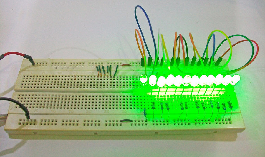
Step 4: Making The Circuit On Breadboard.

Step 5: Move to Perfboard.


Step 6: Wiring time!!
1) Attach wires to each of the LEDs on the perfboard. As you solder each connection, clip the excess lead off the end of the LED.


Step 7: The enclosure
1) Drawing the pattern on the lid with marker for placing the spicer for Arduino. It's really helps for drilling.
2) Be careful when you drilling the "Kitchen Ware" Box, because it made of plastic. It easy to melt if the drill get hot, but it's okay you can tidy it up by using a small cutter knife. Put the spicer 0.5 mm.


Step 8: Put all together
1) Drill the perfboard to attach the nut.


Pin connections:
Top of perfboard
1 Digital Pin 13
2 Digital Pin 12
3 Digital Pin 11
4 Digital Pin 10
5 Digital Pin 9
6 Digital Pin 8
Top of perfboard
1 Digital Pin 13
2 Digital Pin 12
3 Digital Pin 11
4 Digital Pin 10
5 Digital Pin 9
6 Digital Pin 8
7 Digital Pin 7
8 Digital Pin 6
9 Digital Pin 5
10 Digital Pin 4
11 Digital Pin 3
12 Digital Pin 2
13 Digital Pin 1
14 Digital Pin 0
15 Analog Pin 5
16 Analog Pin 4
17 Analog Pin 3
18 Analog Pin 2
19 Analog Pin 1
20 Analog Pin 0
Bottom of perfboard

Step 9: Put the circuit into enclosure.
1) Attach the PCB with nuts to the enclosure.


Step 10: Finish!
You're just finish it right away. The enclosure it's make easier to hold and play it safely.
If you are too lazy to holding it all the time, you can choose the second option that I will give it to you. Just check out step 11 to make it spinning.
Step 11: All you need for making it spinning
This is a quick step to make your POV spinning. So here all you need :
you can build it with your own way, for me I just bought it on the market, and it's originally was a cutting board

I think it's the best choice, because you can run it from 3V to 12V, at 3 volts it only pulled about 20mA and it runs fairly slow, then you can tune your adapter to the speed as fast as you want, but I warned you 12V are fast enough to make your platform shaking like crazy.

I'm using an old pencil case. We're going to use just one side.


- Drill
- Hot Glue Gun
- Cutter
- Foam double tape adhesive
- Gorilla glue
- Super glue
Step 12: Build the platform board
1) Drill the board. Customize the diameter to the size of the dynamo that you used.


Step 13: Assemble all parts and Finish it for the second time!!
Assemble all parts. Try the platform first. Give 3 or 4,5 volts from the adapter to make sure they spinning with balancing.

My Robot Education Sdn. Bhd. (Robotedu.my) was founded in 2015 as the first robotics education centre in Malaysia to provide Arduino-based robotics courses for youths. Our vision is to be able to provide robotics education to every youth in Malaysia.
This comment has been removed by the author.
ReplyDeleteThis comment has been removed by the author.
ReplyDeleteCan you plz send me avr/pgmspace.h library which you have used in your code files.
ReplyDeleteThanx!
best
ReplyDeleteYour efforts are really appreciated and really nice to read your blog you have done everything indepth. keep sharing your efforts with us. Arduino Training in Lahore
ReplyDeleteWebsite : NAGAQQ
ReplyDelete