Showing posts with label LDR. Show all posts

Sunday, August 14, 2016

Mood Lamp with Arduino

Hi! In this tutorial you will learn to make a mood lamp with Arduino.

I know that you may have seen a lot of mood lamp projects with Arduino, but I wasn't very satisfied with them because they all change the color very abruptly. So, I decided to make a smooth mood lamp and I also made it to turn on only when the room is dark.


This project is good for those who are beginners in the Arduino's world.


Step 1: What You Need?

1 x Arduino UNO
1 x USB Type-B Cable
1 x 9V Battery Holder  or  9V Battery Snap
1 x Breadboard  or  Mini Breadboard
1 x RGB LED  or  1 Red & 1 Green & 1 Blue LED
1 x LDR (Light Dependent Resistor)
Male-to-Male Jumper Wires
1 x Computer with Arduino IDE
1 x 9V Battery
1 x Sheet of paper


Don't have components? Don't worry. Just click the component's name. 


Step 2: Write The Code & Upload. 

Write the code above on the Arduino program.
Darker the ambient light is, the higher is the value read from the LDR.
I used PWM to change led's brightness.


Step 3: Build Your Circuit.

Connect wire like the schematic above.


Step 4: It's done!

Try to add a sheet of paper around it to see it more smoothly, the paper acts as a diffuser.
Feel free to modify this project to your way, and tell me your progress. Comments are welcome.

Arduino UNO R3 easy LDR LED project RGB LED

Tuesday, July 26, 2016

Arduino Laser Tag Target System


This tutorial will show you how to construct a basic interactive laser-sensitive target, great for those just getting started with Arduino. This could easily be used as a platform for a laser tag system, or just something fun to play with! It might also drive your cat insane.


Step 1: What You Need?

1 x Blue LED 
4 x Red LED (you could always change the colors or use multicolored LEDs)
3 x Green LED

1 x Computer with Arduino IDE installed
1 x USB Type-B CableMale-to-Male Jumper Wires 

Arduino Uno R3 Acrylic Transparent Casing
Cable Cover
Arduino Compatible UNO Ultimate Starter Kit / Learning Kit
USB To Power Jack Cable


Don't have components? Don't worry. Just click the component's name. 


Step 2: Build Your Circuit.


I built this on a Maker Shield, but you could build this project on anything! This circuit is very straightforward. The four red LEDs are connected to pins 8,9,10,11; the three green LEDs are connected to 2,3,4; and the blue LED is connected to pin 12. (All LEDs are also connected to ground)


The sensor consists of a 5k potentiometer and a photo-resistor. The middle pin on the potentiometer is connected to ground on the Arduino and the other pin on the potentiometer is connected to analogue pin 0, or A0, on the Arduino. The photo-resistor is connected to +3.3 volts on the Arduino and to the A0 pin on the Arduino.

Your almost done!

Step 3: Upload Code To Board.

In it is the program for the Arduino. Now open the file in the Arduino IDE and upload it to your Arduino! Make sure you have the Arduino plugged in to your computer and make sure you have the newest version of Arduino. Once you have the program loaded onto the Arduino, the four red lights should blink on and off in sequence.


Step 4: Have Fun!


Now get a standard 5mw red laser pointer and try pointing it at the photo-resistor! The blue light should turn on and the three green lights should blink on as well. If nothing happens, try adjusting the potentiometer to increase or decrease sensitivity. You can change things in the Arduino program as well. If you are still having issues, let me know in the comments and I might be able to help you.

You could easily use this as a base for a laser tag system with a few modifications to the program. You could also re-program the Arduino to use the green and blue LEDs as a health bar or something. The possibilities are endless! But remember kids, DON'T POINT LASERS IN ANYONE'S EYES!

Arduino UNO R3 Intermediate LDR LED project

Monday, July 18, 2016

Graph


This example shows you how to send a byte of data from the Arduino to a personal computer and graph the result. This is called serial communication because the connection appears to both the board and the computer as a serial port, even though it may actually use a USB cable, a serial to USB and a USB to serial converter.

You can use the serial monitor of the Arduino Software (IDE) to view the sent data, or it can be read by Processing (see code below), Flash, PD, Max/MSP, etc.


Step 1: What You Need?

1 x Arduino Board ( Arduino UNO R3 used in this tutorial.)
1 x Analog Sensor ( Potentiometer, Photocell, etc.)

1 x USB Type-B Cable 
Female-to-Male Jumper Wires 


Software Required


Optional 

You can buy Arduino Compatible UNO Ultimate Starter Kit / Learning Kit at here.


Don't have components? Don't worry. Just click the component's name. 


Step 2: Build Your Circuit.

Connect a potentiometer or other analog sensor to analog input 0.


Step 3: Upload The Code.

1. Select the Arduino board type: Select Tools >> Board >> Select your correct Arduino board used.

2. Find the port number by accessing device manager on Windows. See the section Port (COM&LPT) and look for an open port named "Arduino Uno (COMxx)". If you are using a different board, you will find a name accordingly. What matters is the xx in COMxx part. In my case, it's COM3. So my port number is 3.

Select the right port: Tools >> Port >> Select the port number.

3. You can find this code in the example of Arduino IDE.
Select File >> Examples >> 04.Communication >> Graph


Click press the "upload" button (see the button with right arrow mark).

Processing Sketch

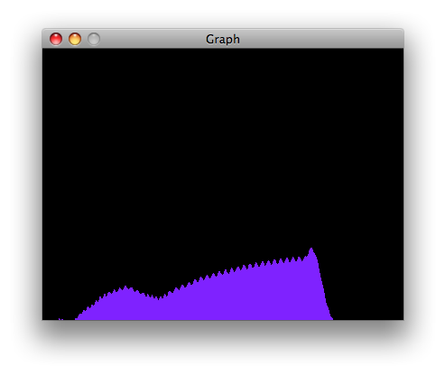
Using the Processing sketch in the code sample above, you'll get a graph of the sensor's value. As you change the value of the analog sensor, you'll get a graph something like this:


Max Code

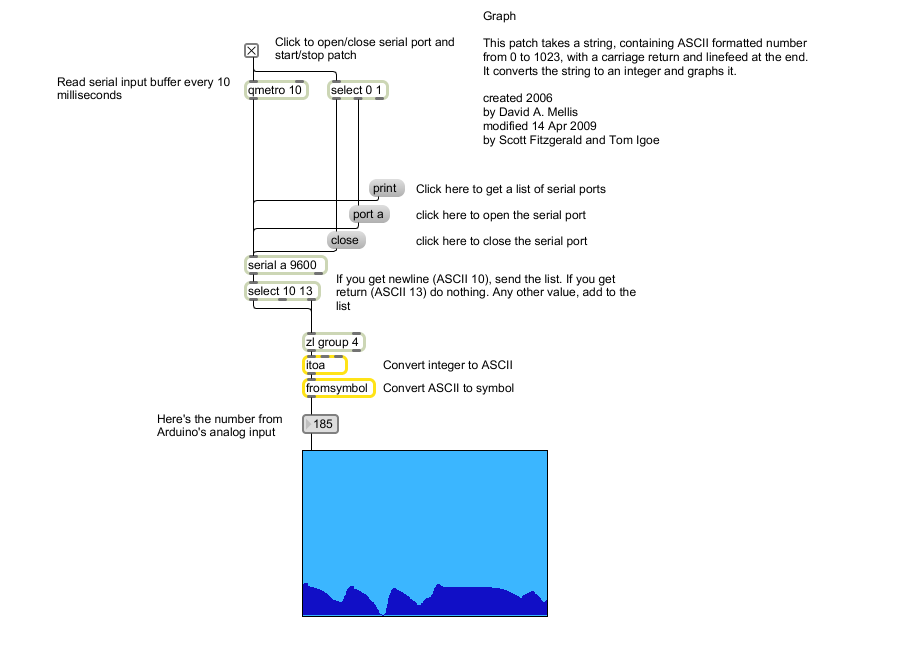
The max patch looks like this. The text of the patch is in the code sample above. Copy the text and paste it into a new Max window to see the sketch.

Arduino Arduino UNO R3 LDR library

Saturday, July 16, 2016

Calibration

This example demonstrates one technique for calibrating sensor input. The board takes sensor readings for five seconds during the startup, and tracks the highest and lowest values it gets. These sensor readings during the first five seconds of the sketch execution define the minimum and maximum of expected values for the readings taken during the loop.

Step 1: What You Need?

1 x Arduino Board (Arduino UNO used in this tutorial)
1 x LED (Red)
1 x 220 Ohm Resistor 
1 x Analog sensor (a photoresistor will do)
1 x 10k Ohm Resistor 
1 x Mini Breadboard
Male-to-Male Jumper Wires 

Don't have components? Don't worry. Just click the component's name. 

Step 2: Build Your Circuit.

Analog sensor (e.g. potentiometer, light sensor) on Analog input 2. LED on Digital pin 9. Connect an LED to digital pin 9 with a 220 ohm current limiting resistor in series. Connect a photoresistor to 5V and then to analog pin 0 with a 10K ohm resistor to ground.


Step 3: Upload The Code.

1. Select the Arduino board type: Select Tools >> Board >> Select your correct Arduino board used.

2. Find the port number by accessing device manager on Windows. See the section Port (COM&LPT) and look for an open port named "Arduino Uno (COMxx)". If you are using a different board, you will find a name accordingly. What matters is the xx in COMxx part. In my case, it's COM3. So my port number is 3.

Select the right port: Tools >> Port >> Select the port number.


3. You can find this code in the example of Arduino IDE.
Select File >> Examples >> 03.Analog >> Calibration

Click press the "upload" button (see the button with right arrow mark).


Before the setup, you set initial values for the minimum and maximum like so:

int sensorMin = 1023;        // minimum sensor value
int sensorMax = 0;           // maximum sensor value

These may seem backwards. Initially, you set the minimum high and read for anything lower than that, saving it as the new minimum. Likewise, you set the maximum low and read for anything higher as the new maximum, like so:

// calibrate during the first five seconds
while (millis() < 5000) {
sensorValue = analogRead(sensorPin);
// record the maximum sensor value
if (sensorValue > sensorMax) {
sensorMax = sensorValue;
}
// record the minimum sensor value
if (sensorValue < sensorMin) {
sensorMin = sensorValue;
}
}
This way, any further readings you take can be mapped to the range between this minimum and maximum like so:
// apply the calibration to the sensor reading
sensorValue = map(sensorValue, sensorMin, sensorMax, 0, 255);


Download: 

Arduino Arduino UNO R3 Basic LDR LED library

Friday, July 15, 2016

Analog Input


In this example, we use a variable resistor (a potentiometer or a photoresistor), we read its value using one analog input of an Arduino and we change the blink rate of the built-in LED accordingly. The resistor's analog value is read as a voltage because this is how the analog inputs work.


Don't have components? Don't worry. Just click the component's name. 


Step 2: Build Your Circuit.

Connect three wires to the Arduino board. The first goes to ground from one of the outer pins of the potentiometer. The second goes from 5 volts to the other outer pin of the potentiometer. The third goes from analog input 0 to the middle pin of the potentiometer.

For this example, it is possible to use the board's built in LED attached to pin 13. To use an additional LED, attach its longer leg (the positive leg, or anode), to digital pin 13 in series with the 220 ohm resistor, and it's shorter leg (the negative leg, or cathode) to the ground (GND) pin next to pin 13.

The circuit based on a photoresistor uses a resistor divider to allow the high impedance Analog input to measure the voltage. These inputs do not draw almost any current, therefore by Ohm's law the voltage measured on the other end of a resistor connected to 5V is always 5V, regardless the resistor's value. To get a voltage proportional to the photoresistor value, a resistor divider is necessary. This circuit uses a variable resistor, a fixed resistor and the measurement point is in the middle of the resistors. The voltage measured (Vout) follows this formula:

Vout=Vin*(R2/(R1+R2))

where Vin is 5V, R2 is 10k ohm and R1 is the photoresistor value that ranges from 1M ohm in darkness to 10k ohm in daylight (10 lumen) and less than 1k ohm in bright light or sunlight (>100 lumen).

Circuit:
Potentiometer:


Photoresistor (LDR):

Step 3: Upload The Code.

1. Select the Arduino board type: Select Tools >> Board >> Select your correct Arduino board used.


2. Find the port number by accessing device manager on Windows. See the section Port (COM&LPT) and look for an open port named "Arduino Uno (COMxx)". If you are using a different board, you will find a name accordingly. What matters is the xx in COMxx part. In my case, it's COM3. So my port number is 3.

Select the right port: Tools >> Port >> Select the port number.


3. You can find this code in the example of Arduino IDE.
Select File >> Examples >> 03.Analog >> AnalogInput

Click press the "upload" button (see the button with right arrow mark).

At the beginning of this sketch, the variable sensorPin is set to to analog pin 0, where your potentiometer is attached, and ledPin is set to digital pin 13. You'll also create another variable, sensorValue to store the values read from your sensor.

The analogRead() command converts the input voltage range, 0 to 5 volts, to a digital value between 0 and 1023. This is done by a circuit inside the microcontroller called an analog-to-digital converter or ADC.

By turning the shaft of the potentiometer, you change the amount of resistance on either side of the center pin (or wiper) of the potentiometer. This changes the relative resistances between the center pin and the two outside pins, giving you a different voltage at the analog input. When the shaft is turned all the way in one direction, there is no resistance between the center pin and the pin connected to ground. The voltage at the center pin then is 0 volts, and analogRead() returns 0. When the shaft is turned all the way in the other direction, there is no resistance between the center pin and the pin connected to +5 volts. The voltage at the center pin then is 5 volts, and analogRead() returns 1023. In between, analogRead() returns a number between 0 and 1023 that is proportional to the amount of voltage being applied to the pin.

That value, stored in sensorValue, is used to set a delay() for your blink cycle. The higher the value, the longer the cycle, the smaller the value, the shorter the cycle. The value is read at the beginning of the cycle, therefore the on/off time is always equal.

Arduino Arduino UNO R3 Basic LDR library

Pitch follower using the tone() function


This example shows how to use the tone() command to generate a pitch that follows the values of an analog input. Using a photoresistor (LDR) your Arduino board becomes a simplified light theremin.

Step 1: What You Need?

1 x Arduino Board (Arduino UNO used in this tutorial)
1 x 8 Ohm Speaker
1 x Light Dependent Resistor (LDR) / Photoresistor
1 x Mini Breadboard
Male-to-Male Jumper Wires 

Don't have components? Don't worry. Just click the component's name. 


Step 2: Build Your Circuit.

Connect one terminal of your speaker to digital pin 9 through a 100 ohm resistor, and its other terminal to ground. Power your photoresistor with 5V, and connect it to analog 0 with the addition of a 4.7K resistor to ground.


Step 3: Upload The Code.

1. Select the Arduino board type: Select Tools >> Board >> Select your correct Arduino board used.


2. Find the port number by accessing device manager on Windows. See the section Port (COM&LPT) and look for an open port named "Arduino Uno (COMxx)". If you are using a different board, you will find a name accordingly. What matters is the xx in COMxx part. In my case, it's COM3. So my port number is 3.

Select the right port: Tools >> Port >> Select the port number.


3. You can find this code in the example of Arduino IDE.
Select File >> Examples >> 02.Digital >> tonePitchFollower


Click press the "upload" button (see the button with right arrow mark).
The code for this example is very simple. Just take an analog input and map its values to a range of audible pitches. Humans can hear from 20 - 20,000Hz, but 120 - 1,500 usually works pretty well for this sketch.

You'll need to get the actual range of your analog input for the mapping. In the circuit shown, the analog input value ranged from about 400 to about 1,000. Change the values in the map() command to match the range for your sensor.


Download: 


Arduino Arduino UNO R3 Basic LDR library photoresistor speaker


  • Copyright © Arduino Tutorial ™ is a registered trademark.
    Designed by Templateism. Hosted on Blogger Templates.