This example shows you how to send a byte of data from the Arduino to a personal computer and graph the result. This is called serial communication because the connection appears to both the board and the computer as a serial port, even though it may actually use a USB cable, a serial to USB and a USB to serial converter.
You can use the serial monitor of the Arduino Software (IDE) to view the sent data, or it can be read by Processing (see code below), Flash, PD, Max/MSP, etc.
Step 1: What You Need?
1 x Arduino Board ( Arduino UNO R3 used in this tutorial.)
1 x Analog Sensor ( Potentiometer, Photocell, etc.)
1 x USB Type-B Cable
Female-to-Male Jumper Wires
Software Required
Optional
You can buy Arduino Compatible UNO Ultimate Starter Kit / Learning Kit at here.
1 x Analog Sensor ( Potentiometer, Photocell, etc.)
1 x USB Type-B Cable
Female-to-Male Jumper Wires
Software Required
Optional
Don't have components? Don't worry. Just click the component's name.
Select the right port: Tools >> Port >> Select the port number.

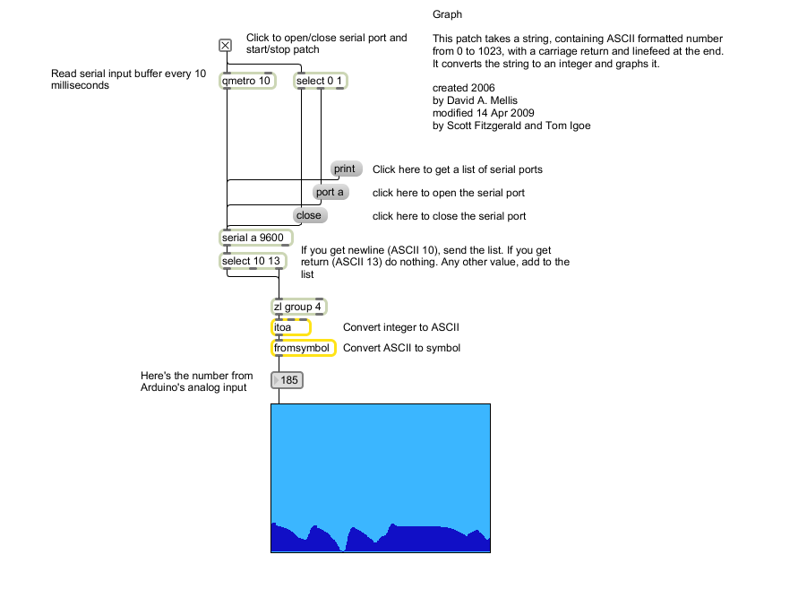
The max patch looks like this. The text of the patch is in the code sample above. Copy the text and paste it into a new Max window to see the sketch.

Step 2: Build Your Circuit.
Connect a potentiometer or other analog sensor to analog input 0.
Step 3: Upload The Code.
1. Select the Arduino board type: Select Tools >> Board >> Select your correct Arduino board used.
2. Find the port number by accessing device manager on Windows. See the section Port (COM&LPT) and look for an open port named "Arduino Uno (COMxx)". If you are using a different board, you will find a name accordingly. What matters is the xx in COMxx part. In my case, it's COM3. So my port number is 3.
Select the right port: Tools >> Port >> Select the port number.
3. You can find this code in the example of Arduino IDE.
Select File >> Examples >> 04.Communication >> Graph
Select File >> Examples >> 04.Communication >> Graph
Click press the "upload" button (see the button with right arrow mark).
Processing Sketch
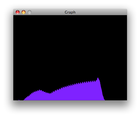
Using the Processing sketch in the code sample above, you'll get a graph of the sensor's value. As you change the value of the analog sensor, you'll get a graph something like this:
Max Code
The max patch looks like this. The text of the patch is in the code sample above. Copy the text and paste it into a new Max window to see the sketch.


0 comments:
Post a Comment