In this project, we'll build a motion-sensing arduino alarm using a PIR (passive infrared) sensor and an Arduino UNO. This is a great way to learn the basics of using digital input (from the sensor) and output (in this case, to a noisy buzzer) on Arduino board.
This Arduino alarm is handy for booby traps and practical jokes, and it's just what you'll need to detect a zombie invasion! Plus, it's all built on a breadboard, so no soldering required!
Step 1: What You Need?
1 x Arduino UNO R31 x Breadboard
1 x PIR sensor
1 x LED (RED) (5mm)
1 x Buzzer
1 x Female-to-Female Jumper Wire
1 x Computer with Arduino IDE software
Don't have components? Don't worry. Just click the component's name.
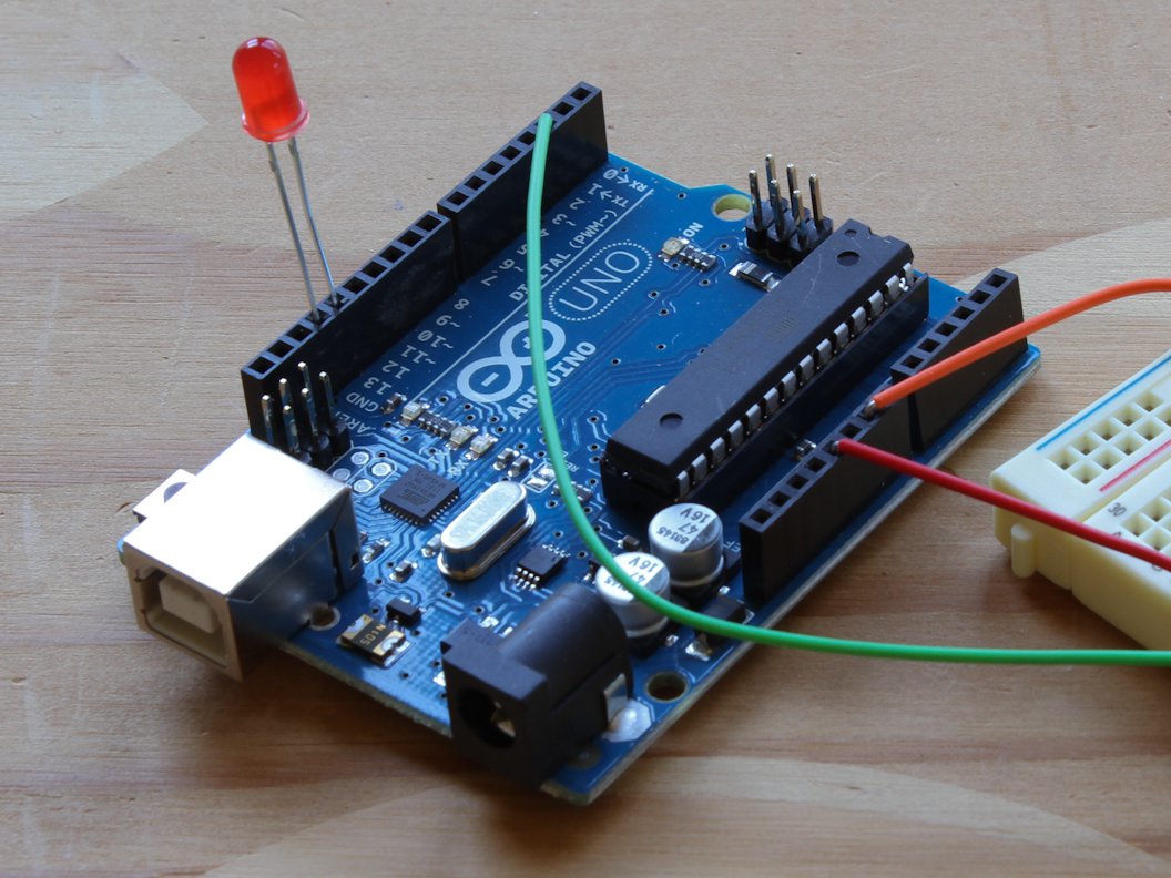
Step 2: Wire Arduino Board To Breadboard.
- Connect digital input/output (I/O) pin 2 on the Arduino UNO to row 1 on the breadboard. (Green color wire)
- Connect the 5V pin on the Arduino UNO to row 2 on the breadboard (Red color wire), and connect a nearby ground (GND) pin to row 3 (Orange color wire).

Step 3: Connect Your Motion Sensor.

- Plug the PIR sensor into the breadboard so that its (-) pin connects to the Gnd row, its (+) pin connects to 5V, and its Output pin connects to digital pin 2.

(NOTE: If you have a different sensor that the one shown here, you may need to extend the sensor's pins with a stacking female header, wires, interconnect cables, etc. to fit.)
Step 4: Plug In the LED.
- Plug the LED's anode (longer leg) into digital pin 13 on the Arduino.- Plug the LED's cathode (shorter leg, and/or the leg on the flattened side of the LED base) into the adjacent ground (Gnd) pin on the Arduino.

Step 5: Connect The Piezo Buzzer.
- Connect the Vcc on the Buzzer (Red color wire in image) to the Arduino's digital pin 10.- Connect the Gnd on the Buzzer (Black color wire in image) to the Arduino's Gnd pin.
(NOTE: These two wires can be reversed, as the polarity of the buzzer doesn't matter.)

Step 6: Program the Arduino.
- Plug the USB cable into your computer and Arduino UNO.- Set the board and port settings for your Arduino Board.
Board: Arduino UNO
- Open the sketch and upload to board.
Step 7:Test Your Alarm.
- When you power up your alarm, the PIR sensor will glow an ominous red. Stand very still or leave the room while the alarm calibrates the infrared level reading for the room.- Now test it by moving: the buzzer will buzz and the LED will light up.
- Be amazed! Your PIR Sensor Arduino Alarm can sense movement up to 20 feet away.
(NOTE: Might not be reliable for detecting the undead.)

Download:
Arduino softwareSources:[http://makezine.com/projects/pir-sensor-arduino-alarm/]

My Robot Education Sdn. Bhd. (Robotedu.my) was founded in 2015 as the first robotics education centre in Malaysia to provide Arduino-based robotics courses for youths. Our vision is to be able to provide robotics education to every youth in Malaysia.


0 comments:
Post a Comment