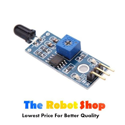
Step 1: What You Need?
1 x Any Arduino Board (Arduino UNO used in this tutorial.)
1 x Flame Sensor (With Analog Output)
1 x Lighter Or Another Flame Source For Testing
Female-to-Male Jumper Wires (FM)
1 x Flame Sensor (With Analog Output)
1 x Lighter Or Another Flame Source For Testing
Female-to-Male Jumper Wires (FM)
Don't have components? Don't worry. Just click the component's name.
Step 2: Build Your Circuit.
Flame sensor ............... Arduino
VCC............................... 5v
GND...............................GND
D0.................................. Analog in 0
Step 3: Testing and Troubleshooting.
Testing:
To test the Flame Sensor and ensure that it is working correctly connect the VCC to a 5v power source and GND. Move a flame source with in a foot of the front of the Ir sensor and the D0-LED should light up.
Troubleshooting:
If the D0-LED does not light up check the following:
- Is the power source 5v?
- Is the ground hooked up?
- Is the flame with in 1 foot and in Line of Sight?
If none of the previous makes the D0-LED light up, your sensor may be defective.
Step 4: Upload The Code.
The following code maps and reads the analog values given by the flame sensor (0-1024). The stock flame sensor will have the following reaction with this code:- If holding a flame within 1.5 feet in front of the sensor; "case 0" will be activated and " ** Close Fire ** " will be sent to the serial monitor.
- If holding a flame between 1.5 feet and 3 feet in front of the sensor; "case 1" will be activated and " **Distant Fire** " will be sent to the serial monitor.
- If no flame is detected in front of the sensor; "case 2" will be activated and "No Fire " will be sent to the serial monitor.
* To view the output, point a serial monitor such as Putty at your Arduino.
* This code is constantly updating in order to provide a real time feedback of the flame sensor.
Thanks for reading.


0 comments:
Post a Comment