Basic Low Cost (<RM300) Arduino Autonomous Sumo Robot
This autonomous is suitable for standard autonomous sumo robot competition which use black color game field with white color boundary.
Wiring:
1. Solder dean connector to AWG 16 red & black wire (20cm)
2. Solder wire (red & black) to both motor.
Arduino Pin #
Connect to
VIN
BATTERY POSITIVE (+)
5V
5V / VCC from sensor
GND
BATTERY NEGATIVE (-),
GND from sensor
A2
Left Ultrasonic (TRIG)
A3
Left Ultrasonic (ECHO)
A4
Left IR SENSOR (Yellow)
A5
Right IR SENSOR (Yellow)
2
Right Ultrasonic (TRIG)
3
Right Ultrasonic (ECHO)
5
MOTOR DRIVER (IN1)
6
MOTOR DRIVER (IN2)
9
MOTOR DRIVER (IN3)
10
MOTOR DRIVER (IN4)
Motor Driver Pin
Connect to
12V
BATTERY POSITIVE (+)
GND
BATTERY NEGATIVE (-)
OUT1
Left Motor (any side)
OUT2
Left Motor (another side)
OUT3
Right Motor (any side)
OUT4
Right Motor (another side)
IR Sensor Pin
Connect to
RED WIRE
5V from Arduino
GREEN WIRE
GND from Arduino / battery
YELLOW WIRE
A4 & A5 from Arduino
Programming:
Troubleshooting:
1. Check IR sensor for color detection. black (LED off) & white (LED on) by changing the sensitivity using potentiometer from IR sensor.
2. If ultrasonic cannot detect object, then increase the value of "MAX_DISTANCE" from Arduino line 3 & 4.
3. If motor run different direction, exchange connection from IN1 & IN2 (IN3 & IN4) jumper cable pin.
Note:
1. Don't overuse your LiPo battery until less than 11.1V.
Alright! So the idea struck out of blue one day when I was shocked to see someone sitting outside my office enjoying reading a newspaper!
I had no idea who this person was, when did he come and since how long was he enjoying his unsolicited stay just outside my cabin? You must be thinking what a fool I am but you gotta trust me on this, my office is one of the creepiest that one can get anywhere. Seriously!
I had an Arduino UNO clone ready at my disposal. So, all that I needed was an ultrasound sensor, and a Buzzer. Rest of the steps, circuit assemblies, software code are ensued in this tutorial. I hope this would excite few electronics newbies out there.
This is a nice project that you can continue to work on and modify as you learn more Arduino projects. This tutorial goes through the complete build for the bluetooth enabled robot in the first half of the video. It takes in total about 35 hours to 3D print, but can be assembled and programmed in around 30 minutes. Requires only 2 screwdrivers to build and does not require any soldering.
I wanted to design this thing to be inexpensive and use common parts, so this robot uses 9V batteries currently. They run out pretty quickly with a lot of use, so I will probably end up designing a new piece that allows for the use of rechargeable lithium ion batteries and Adafruit power booster.
Step 3: Lightly Sand Wheels and Put Together Legs.
The wheels print in two pieces so use super glue and put them together. Lightly sand out the imperfections. Put the 4 balls inside the castors and push them all the way until they snap into place. Attach the 4 castors to the legs like in the below picture.
Step 4: Get the legs ready and add the geared DC motors.
Get the two posts in the first picture and connect each one to each leg. Get the piece that will hold the battery in the second picture and screw that into one leg.
Find the small L shaped piece and attach it to a motor exactly like the 4th picture shown above. Do the same thing with the other motor, and attach both to the legs. Meet the two legs together, being sure the motors are facing the same direction and you should have something exactly like the picture below.
Step 5: Add battery with box and complete base.
Find the two curved side pieces in the first picture and connect them to the base according to the second picture. Place the battery box with battery onto the base according to the third picture and find the battery back piece and use it to enclose the battery like the last picture. The base is not complete.
Step 6: Add the middle pieces to the base and add the range sensor and motor driver.
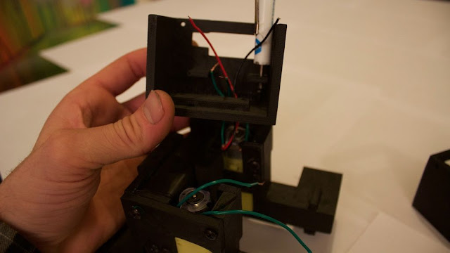
- First use a skinny screwdriver and start the screw in the (robot's) left side middle piece according to the first picture. Its a tight fit and the screw will barely fit under that tab, I have broken the tab off many times, but luckily you have super glue and its an easy fix.
-Pull both battery wires and left side motor wires through the hole and tighten the screw you started. Tighten the second screw and secure the left side piece. Add the faux servo piece to this side and tighten both screws that hold it in, as in the third picture.
-Attach all 4 male to female wires to the HC-SR04 range sensor, it doesn't really matter what colors you use as long as they are different colors and you write down what color goes to what pin on the sensor.
-Put the range sensor into the whole on the side piece like in the 5th picture and put the L298N motor driver on top. You must remove the two jumpers on the motor driver shown in the 6th picture.
-Attach the wires from the battery and the left side motor to the L298N motor driver according to the diagram. Add some male to female (or male to male) wires coming from the positive and negative terminals of the motor driver.
-You will have now two connections in the negative terminal, one going in and one coming out. Just to be clear it will look like the 7th picture (above).
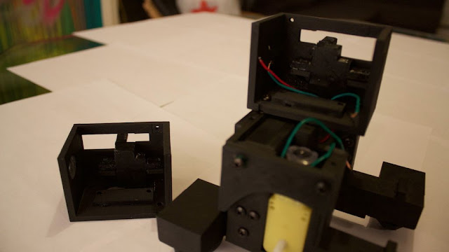
-Grab the right side middle piece and add the other faux servo piece to that side with two screws.
-Now pull the right side motor wires through the right side piece and attach those wires to the motor driver. Try to attach them in order, i.e. left side wire to left most hookup on the driver (same thing on the other side), that way you don't have to change anything in the code later.
-Use two screws to secure the right side piece, and use two screws to secure the motor driver, one per side piece is fine but there are holes to add all 4 if you want.
-Finally, add 6 different color male to female jumper wires to the 6 pins on the motor driver.
Step 7: Almost there.
-Use a screwdriver and add slack to the positive and negative battery wires as shown in the first picture (makes it easier for the battery to slide out the side when you need to change it).
- Attach the claws to the arms and attach those to the shoulder pieces as shown in the first picture. Attach the arms to the faux servo pieces, as in the second picture.
-Find the neck piece in the third picture and attach the C shaped piece (file name neckNoServo.stl) with two screws from the bottom. Pull all the wires through that assembly. Attach the neck assembly with 4 screws to the base that you have so far.
-Add the head bottom piece and pull the wires through that try to use the orientation of the wires in the 4th and 5th picture. Range sensor wires through the left most hole (robot's right), motor driver wires through the center, and power and ground through the right most hole. Attach 4 male to female connectors to you bluetooth module and tape them together if possible. It is going to go underneath your Arduino board like in the last picture. This is down so it can be unplugged easily when uploading new sketches.
-Wire everything according to the diagram.
Step 8: Done.
Attach the two halves of the face with 4 screws. Find the ears/antennae and attach them to filename earsNoServo.stl. They should now look like the T shaped pieces in the first picture. Attach them to the head top piece. Each one has two screws. Put the face piece on and pop the LEDs into the eyes, bending the pins at a 90 degree angle so they can't fall off like in the second picture.
Step 9: Upload the code and Download app.
Download the Android apps in the two pictures below.
Pair your bluetooth module to your computer or phone with the password "1234" it will be called HC-06.Everything else is pretty straight forward to use, if you watched the video, the apps are pretty intuitive to use.
To control the robot via bluetooth from you computer connect the serial monitor to bluetooth port HC-06 and use these commands with CAPITAL LETTERS (put caps lock on) and hit enter after each command:
S = stop, F = forward, B = backward, L = left, and R = right.
IMPORTANT*** anytime you need to upload a new sketch the bluetooth module must be unplugged or else the code will not upload.
The automatic watering system simple just read the water level in the water bowl with a HC-SR04 Ultrasonic Sound Sensor. It measure the distance to the surface of the water. If the level is less then 3cm for more than 30sec it triggers a 5V relay whit a NO-contact . The relay are controlling a 12V DC supply to a mini watering pump in the water tank.
Hey everyone today I want to show you how to make an Arduino-controlled lie detector to see when your friends are lying to you or to measure the different responses that your bodies skin goes through depending on the situation you are in or the emotions you are feeling and the coolest thing of all is that we can see all of theses things happen in real time in an Arduino graph.
Our skin is amazing! It provides a medium for us to experience the sense of touch, it keeps infections out and keeps innards in but I bet you didn't know that our skin changes conductivity depending on many different things one being our mood! It called Electrodermal activity (EDA) and there's a really interesting Wikipedia page you can read here. The basics are that our skin changes its conductivity depending on how we feel.
We have to start by asking the subject some easy questions we know they will answer truthfully like "what is your name" and "where do you live" to get a baseline and from there we can start asking questions that they may lie about, if they do they would probably feel nervous and then we can read the changein the base line that be established earlier if they lie.
Don't have components? Don't worry. Just click the component's name.
Step 2: Build Your Circuit.
The wiring for this is pretty easy, we will start by connecting them in this order:
Connect a long piece of cable to Arduino analog pin 0.
Connect the 2k resistor to ground and the the extended analog 0 pin.
Connect a long piece of cable to Arduino 5 volt pin.
Connect the anode (long leg) of the green led to pin 2 and the cathode (short leg) to ground.
Connect the anode of the orange led to pin 3 and the cathode to ground.
Connect the anode of the red led to pin 4 and the cathode to ground.
That's all the wiring for the Arduino, now we need a way to keep the sensor wires on our fingers we will cover this later.
Step 3: Upload The Code.
The main piece of software we are going use is the newest version on the Arduino IDE. The new update brings a new way to see the data being received from the Arduino, instead of being in text form from the serial monitor, it can now be displayed in a real time graph which will help us identify when the data changes its pattern (when someone lies)
To open the plotter open Arduino and navigate to the tools menu and you should see it there just below serial monitor.
Step 4: Making The Finger Clips.
Now that the basic form of the project is done we can start adding features to make it easier to use we will start by adding finger clips to keep a stable connection between our fingers and the cables.
Lets start by gluing a strip of tinfoil to the bottom of a strip of velcro, do this for both pieces of velcro (the hook and the loop. Now rap it around your finger until it makes a tight fit (check photos) then tape the exposed wire from analog pin 0 to the tin foil and repeat this step for the 5 volt pin (make sure it makes a good connection).
Step 5: Making The Case.
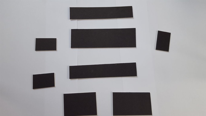
The plan is to make a small compartment for the finger pads to fold away and to have three holes for the LEDs to stick out. Its going to be made out of cardboard and to make it we will need to cut the following shapes out:
Cut two 15x3 cm rectangles
One 15x5 cm rectangle
Three 5x3 cm rectangles (cut a square in the middle on one of them for the nano usb)
One 9x5 cm rectangle
One 6x5 cm rectangle
The 15x5 rectangle is the base. The two 15x3 rectangles and two of the 5x3 rectangles get glued to the sides of the base. Now glue the third 5x3 rectangle to the base 6cm from the side (close to the middle, check photos) Now you should have a rectangle that's divided into two sides, one with a length of 6cm and the other with a length of 9cm. The side with a length of 6cm is where we are going to put the electronics and the other side is where the finger pads go. Next cut 3 holes (the size of LEDs) on the 6x5 rectangle and glue it down to the 6cm side (as a lid). Last we need to tape the short side of the 9x5 rectangle to the far side of the 9cm side (this acts as a lid that flips up and down to reveal the finger pads).
Step 6: Putting It All Together.
The last thing we need to do is put the electronics in the case start by gluing down the Arduino and all wires in the 6cm side and run the extended wires (pin analog 0 and 5 volt) to the other side of of the rectangle (9cm side). Now glue the three LEDs to the holes we made on the 6x5cm rectangle and give it a test if all goes well you should have a small portable Arduino lie detector but let me warn you this isn't the most accurate system in fact most real lie detectors use a host of other sensors to determine if someone is lying such as a heart rate monitor and others, what I'm saying is don't uses the result of this for serious questions.